Laser device for material processing

a laser beam and material technology, applied in the field of laser beam monitoring devices, can solve problems such as high degree of complexity of systems, and achieve the effect of facilitating inline monitoring of laser beams

Active Publication Date: 2019-11-05
ALCON INC
View PDF9 Cites 3 Cited by
  • Summary
  • Abstract
  • Description
  • Claims
  • Application Information

AI Technical Summary

Benefits of technology

[0007]On the other hand, the present disclosure facilitates inline monitoring of a laser beam not by the production of a higher harmonic from the basic wavelength of the laser beam, but by power measurements on the basis of single-photon absorption and two-photon absorption. A laser device for material processing is accordingly provided according to certain embodiments, comprising a source of a pulsed laser beam, a detector system for the photodetection of a plurality of partial beams generated from the laser beam by radiation outcoupling and provision of corresponding detection signals, and an evaluation unit linked to the detector system for evaluation of the detection signals, wherein a first of the detection signals is based on single-photon absorption and a second of the detection signals is based on two-photon absorption. The two-photon absorption is based on the process that a molecule passes from a basic state to an excited state if the molecule absorbs two photons simultaneously. A detector operating on the principle of two-photon absorption has a suitably chosen band gap between the basic state and the excited state, so that for a given wavelength of the laser radiation it only emits a detection signal if two-photon absorption events occur. In contrast to this, in single-photon absorption a single photon is sufficient to cause a transition of a molecule to an excited state.

Problems solved by technology

Ultrashort pulse lasers, especially those delivered as “turnkey” systems to customers by a laser manufacturer, are systems with a high degree of complexity, which usually require constant monitoring and adjustment of the pulse parameters to maintain the efficacy of the material processing at a desired level.

Method used


Image

  • Laser device for material processing

Examples


Embodiment Construction

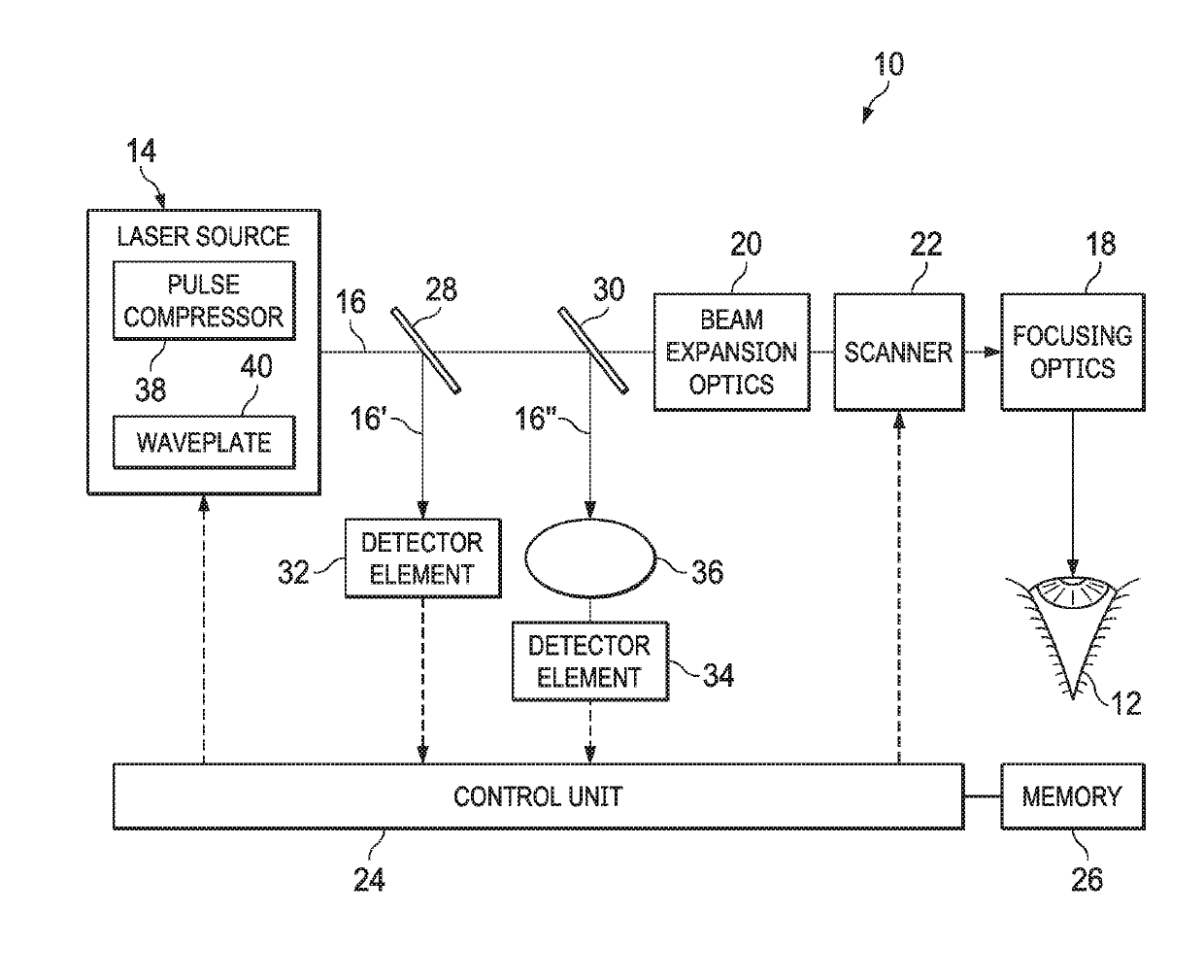
[0016]Preferred embodiments are explained in greater detail below with reference to FIG. 1. This shows a device, generally designated by 10, for laser-aided material processing. In the example shown, the laser device 10 is used for laser processing of a human eye 12 and for producing intracorneal tissue sections there, for example. In principle, however, the present disclosure is not limited to the use of the laser device 10 in laser-aided eye surgery. Instead of this, the laser device 10 can also be used in particular for cutting laser processing of other biological tissue as well as of non-biological material.

[0017]The laser device 10 comprises a laser source 14, which produces a pulsed laser beam 16 with pulse durations in the pico-, femto- or attosecond range. The laser device 10 also comprises focusing optics 18, which are formed by an F-Theta lens, for example. The focusing optics 18 focus the laser beam 16 onto the object to be processed, here the eye 12. Also arranged in the...


PUM

PropertyMeasurementUnit
energy densityaaaaaaaaaa
transparentaaaaaaaaaa
energy densityaaaaaaaaaa

Abstract

In certain embodiments, a laser device for laser processing of an eye comprises a source of a pulsed laser beam, a detector system that photodetects partial beams generated from the laser beam, and a control unit that evaluates the detection signals. A first detection element of the detector system provides a first detection signal based on single-photon absorption. A second detection element provides a second detection signal based on two-photon absorption. The control unit puts the measured signal strengths of the two detection signals into a ratio to one another. Variations in the resulting ratio value may be traced back to variations in the pulse duration and / or wave front of the laser beam. The control unit may initiate countermeasures to maintain the beam quality of the laser beam.

Description

CROSS REFERENCE TO RELATED APPLICATIONS[0001]This application claims priority to German Patent Application Serial Number 10 2017 002 434.0, filed 13 March, titled “LASER DEVICE FOR MATERIAL PROCESSING,” which is hereby incorporated by reference in its entirety.FIELD[0002]The present disclosure relates to a laser device for material processing.BACKGROUND[0003]The importance of ultrashort pulse lasers for processing a wide range of materials is increasing more and more. In particular, ultrashort pulse laser radiation can be used to produce cuts in transparent materials (transparent for the radiation wavelength) deep in the material, i.e. below the surface. In the case of the short pulse durations in question here in the range of pico-femto- or attoseconds, the non-linear interaction processes between laser radiation and material that are responsible for the material separation (disruption) are concentrated mainly on the region of the beam focus, so that a high cutting accuracy can be ...

Claims


Application Information

Patent Timeline
Patent Type & Authority Patents(United States)
IPC IPC(8): A61F9/008B23K26/70H01S3/00A61N5/067B23K103/00
CPCH01S3/005A61F9/0084A61F9/008B23K26/705A61F9/00825B23K2103/32A61F2009/00872A61N2005/067A61F2009/00844A61N5/067
Inventor VOGLER, KLAUSKITTELMANN, OLAFBUETTNER, EDLEFPOPIEN, JAN
Owner ALCON INC
Why Eureka
Try Eureka