

Polished-rod thermal imaging system for preventing failures in the operation of a sucker rod pump
a technology of thermal imaging system and sucker rod pump, which is applied in the direction of optical radiation measurement, survey, and wellbore/well accessories, etc., can solve the problems of inability to accurately measure the pressure of increase the temperature, and the sucker rod pump is easily damaged, and achieves the effect of reducing calibration and operator intervention, and being convenient to install and opera
- Summary
- Abstract
- Description
- Claims
- Application Information
AI Technical Summary
Benefits of technology
Problems solved by technology
Method used
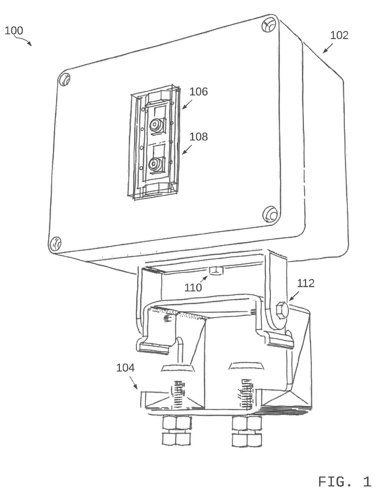
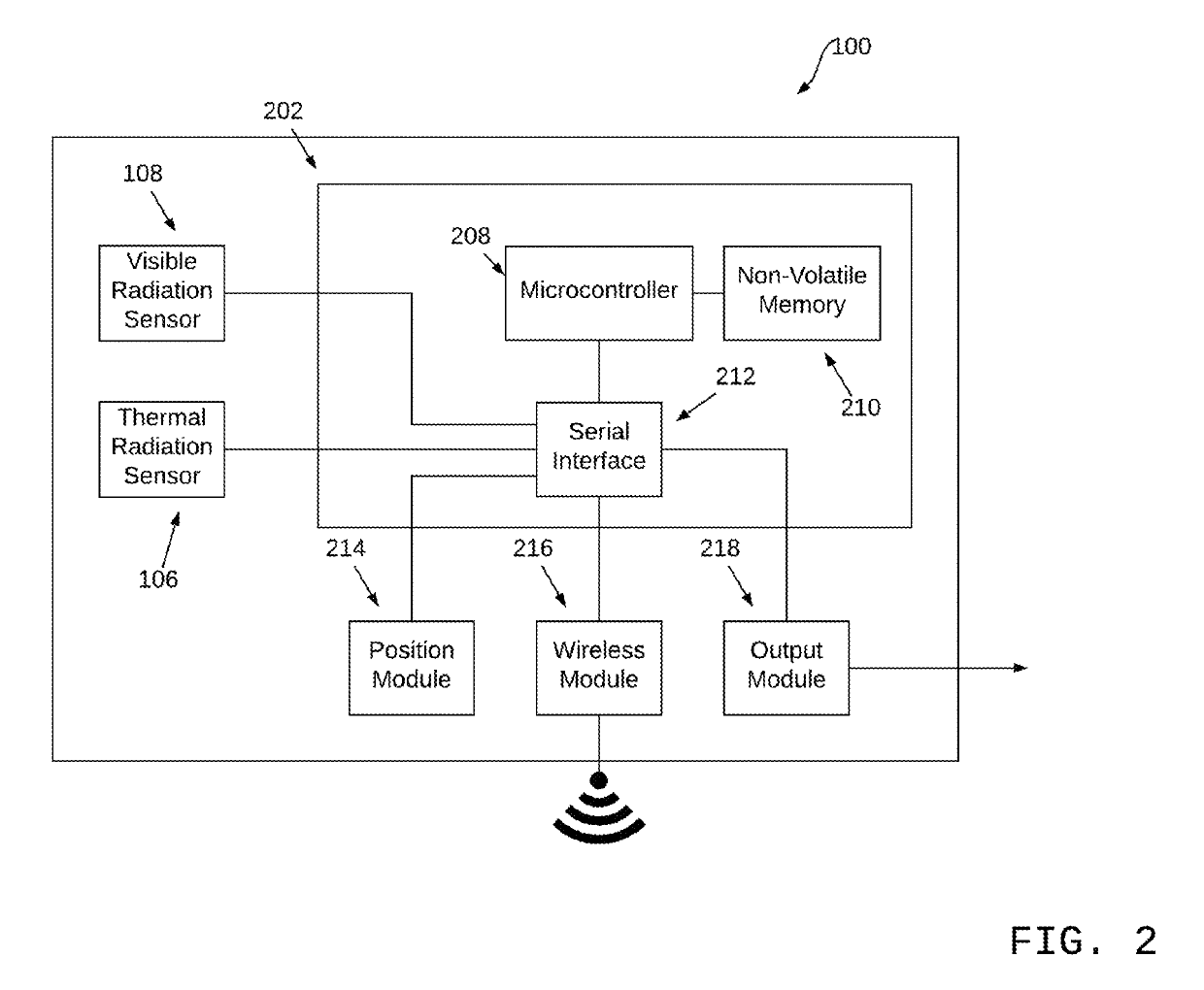
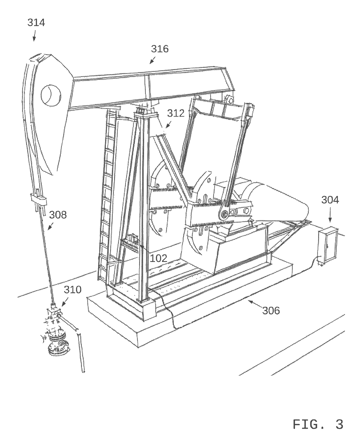
Image

Examples
Embodiment Construction
[0036]The following is a detailed description of exemplary embodiments to illustrate the principles of the invention. The embodiments are provided to illustrate aspects of the invention, but the invention is not limited to any embodiment. The scope of the invention encompasses numerous alternatives, modifications and equivalent; it is limited only by the claims.
[0037]Numerous specific details are set forth in the following description in order to provide a thorough understanding of the invention. However, the invention may be practiced according to the claims without some or all of these specific details. For the purpose of clarity, technical material that is known in the technical fields related to the invention has not been described in detail so that the invention is not unnecessarily obscured.
Definitions—as Used Herein
[0038]A. Microcontroller—Refers without limitation to any microprocessor design that preferably emphasizes high integration, low power consumption, self-sufficienc...
PUM
 Abstract
Description
Claims
Application Information