DC brushless ceiling fan speed control device and method

Active Publication Date: 2019-11-05
RHINE ELECTRONICS
View PDF3 Cites 2 Cited by
  • Summary
  • Abstract
  • Description
  • Claims
  • Application Information

AI Technical Summary

Benefits of technology

The switch module in this patent can be used in various types of switches to prevent unnecessary power consumption and safety issues. It provides good convenience and safety while saving energy.

Problems solved by technology

When the control switch 27 is situated at a stop gear position, only the operation of the ceiling-fan brushless motor 30 is stopped, but the control switch 27 is still situated at an electrically connected status to continue inputting power, and such continual supply of power will consume or waste energy unnecessarily or create an unsafe factor to the ceiling-fan brushless motor 30.
Obviously, the use of such structure is inconvenient and the conventional devices and method require further improvements.

Method used


Image

  • DC brushless ceiling fan speed control device and method
  • DC brushless ceiling fan speed control device and method
  • DC brushless ceiling fan speed control device and method

Examples


Embodiment Construction

[0014]The technical contents of the present invention will become apparent with the detailed description of preferred embodiments accompanied with the illustration of related drawings as follows. It is intended that the embodiments and figures disclosed herein are to be considered illustrative rather than restrictive.

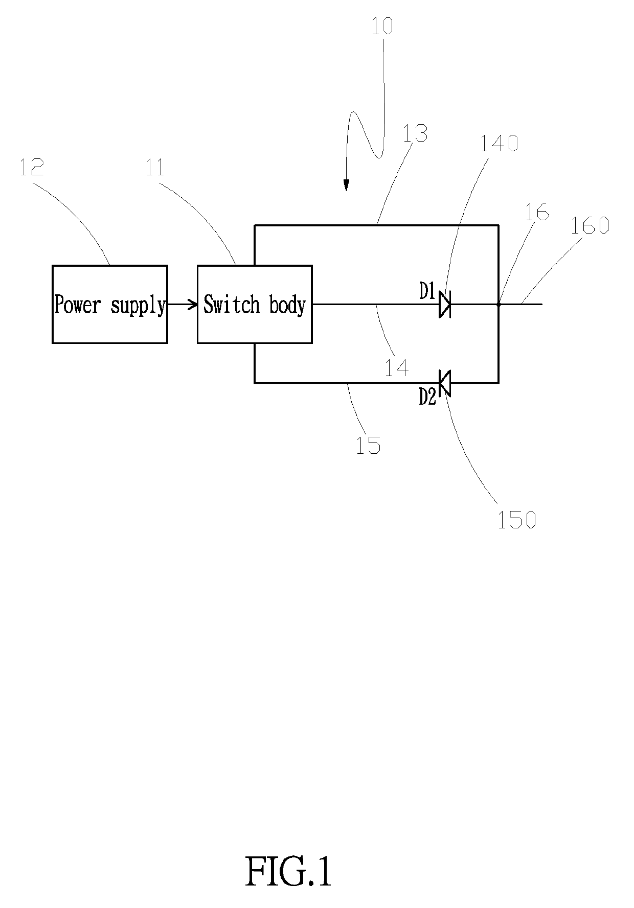
[0015]With reference to FIG. 1 for a schematic circuit block diagram of a DC brushless ceiling fan speed control device in accordance with the present invention, the DC brushless ceiling fan speed control device comprises:

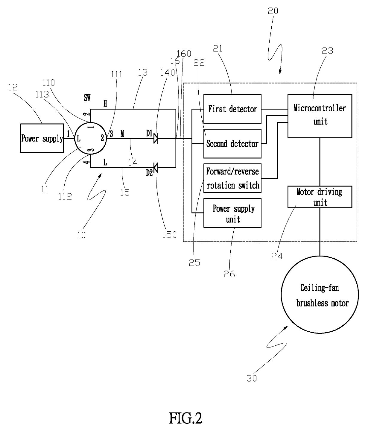
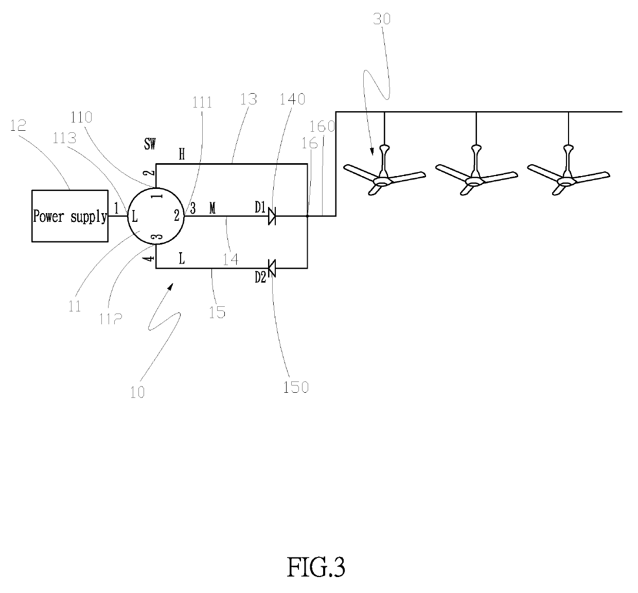
[0016]a switch module 10, including a switch body 11, a power supply 12 coupled to a side of the switch body 11, and a first wire connecting member 13, a second wire connecting member 14 and a third wire connecting member 15 coupled to the other side of the switch body 11, and the second wire connecting member 14 having a forward diode 140, and the third wire connecting member 15 having a reverse diode 150, and the first wire connecting member 13, seco...


PUM


Abstract

In a DC brushless ceiling fan speed control device and method, the control device includes a switch module having a switch body, a power supply connected to a side of the switch body, and first, second, and third wire connecting members connected to the other side of the switch body. The second and third wire connecting members have a forward diode and a reverse diode respectively, and the switch body is provided for controlling the input of a power supply to directly and electrically supply power to the first wire connecting member, or supply power to the second and third wire connecting members through the forward and reverse diodes. When current is inputted, the waveform signal will be different, and this phenomenon is used for controlling the rotating speed of a ceiling fan to achieve the effects of good safety and convenience.

Description

FIELD OF THE INVENTION[0001]The present invention relates to a DC brushless ceiling fan speed control device and its control method, and more particularly to the device and method for controlling the rotating speed of a ceiling fan.BACKGROUND OF THE INVENTION[0002]With reference to FIG. 6 for a conventional ceiling fan control structure, the ceiling fan control structure is comprised of a control circuit board 20 and a ceiling-fan brushless motor 30, and the control circuit board 20 has a microcontroller unit 23, a control switch 27 and a remote control receiving unit 28, and the remote control receiving unit 28 has a wireless receiver 280, wherein the control switch 27 or the remote control receiving unit 28 is operated to control the microcontroller unit 23 to change the rotating speed of a ceiling-fan brushless motor 30, and the control switch 27 includes a stop gear position contact and a gear changing position contact (not shown in the figure). When the control switch 27 is sit...

Claims


Application Information

Patent Timeline
IPC IPC(8): H02P6/08F04D25/08
CPCF04D25/088H02P6/08F04D27/004H02P7/28Y02B30/70
Inventor LIAO, YIN SHENG
Owner RHINE ELECTRONICS
Why Eureka
Try Eureka