
Detachable device, control circuit, control circuit firmware program, information processing method and circuit design pattern in control circuit, and log-in method

a technology of control circuit and removable device, applied in the direction of program control, unauthorized memory use protection, instruments, etc., can solve the problem of limited access to the second unit device, and achieve the effect of superior convenience and security, and compact siz

Inactive Publication Date: 2006-08-03
SASLITE CORP
View PDF6 Cites 91 Cited by
  • Summary
  • Abstract
  • Description
  • Claims
  • Application Information

AI Technical Summary

Benefits of technology

[0022] In these embodiments, sending the computer a signal simulating a first unit device as a device of a specified type (for example, a CD-ROM drive), on which automatic startup of programs, etc. is to be run, causes the execution of the desired scripts or programs (hereinafter called “programs, etc.”) to be started even if a peripheral device utilizing a USB memory, etc. is used, and a different second unit device is recognized afterwards, at a predetermined timing. As a result, access to the second unit device is limited to the programs etc., which makes it possible to maintain secrecy. In this manner, providing a time difference between the automatic startup of the programs etc. and recognition makes it possible to offer a removable device of superior convenience and security.
[0076] In this embodiment, server login is automated, which makes processing faster and easier both when the user receives certain membership services from the server as a result of login and when the user is identified in order to narrow down the target audience of advertising. In addition, the automatic login performed by the program reduces the risk of passwords being recorded and misused by spyware or by a password cache on a borrowed personal computer. In addition, various management functions, such as changing advertisers or establishing access rates for each member, are rendered reliable and easy by logging in via a relay server.

Problems solved by technology

As a result, access to the second unit device is limited to the programs etc., which makes it possible to maintain secrecy.

Method used


Image

  • Detachable device, control circuit, control circuit firmware program, information processing method and circuit design pattern in control circuit, and log-in method
  • Detachable device, control circuit, control circuit firmware program, information processing method and circuit design pattern in control circuit, and log-in method
  • Detachable device, control circuit, control circuit firmware program, information processing method and circuit design pattern in control circuit, and log-in method

Examples


first embodiment

[0121] 0. Outline of First Embodiment

[0122] The first embodiment facilitates the use of data that only the owner of the device stores in a connected personal computer, in a USB memory-type device, in which e-mail and other personal information is stored.

[0123] To implement the device, the device of the first embodiment is furnished with a CD-ROM compatible region for storing applications and other dedicated software programs and a so-called “autorun” function for automatically starting programs from this region. In addition, it has an HDD-compatible region for data storage. The device has a storage region and command transmitting means that can be used only from the dedicated programs and can connect / disconnect the regions based on specified commands from the dedicated programs.

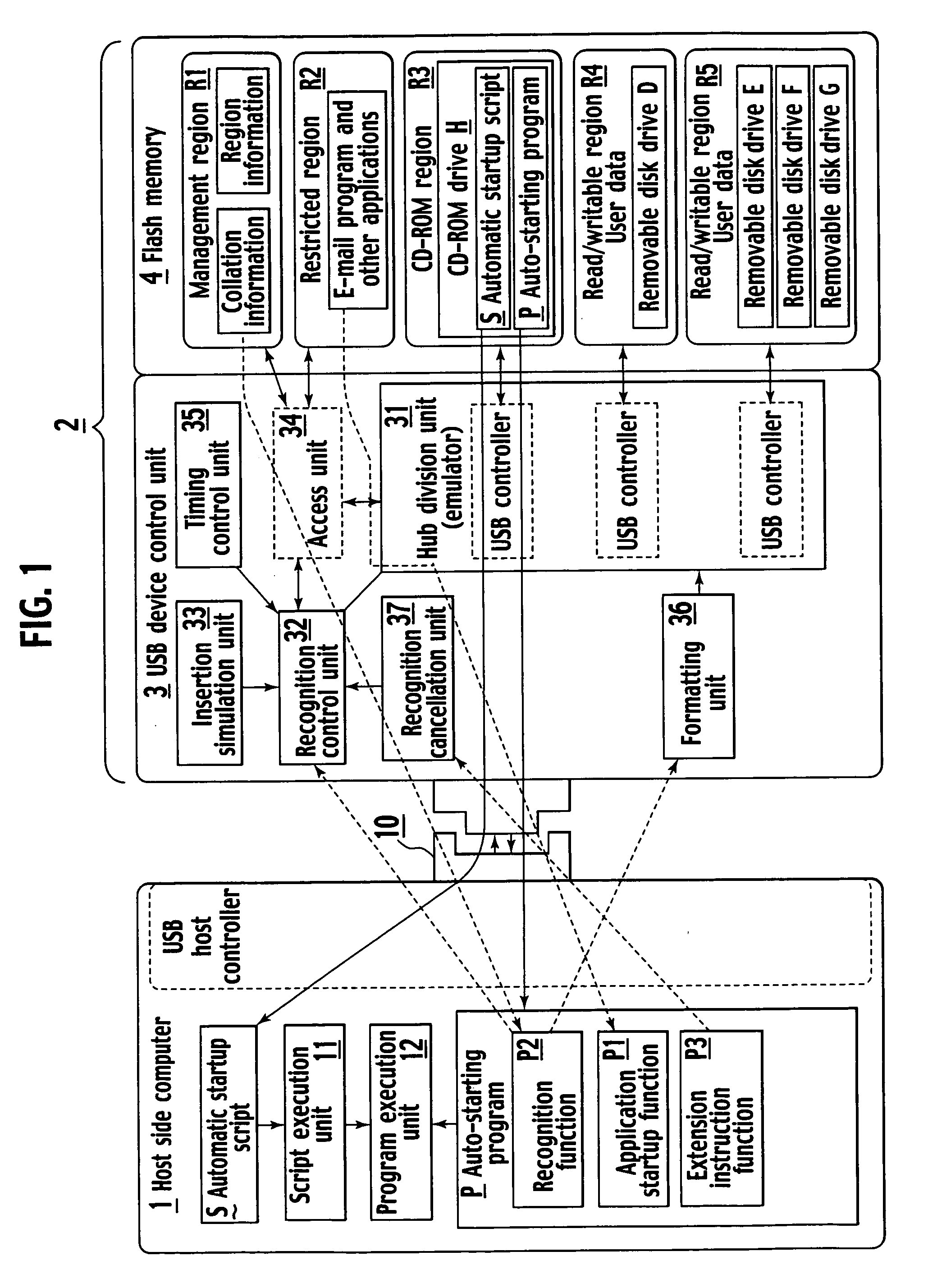
[0124] 1. Configuration of First Embodiment

[0125] First of all, FIG. 1 is a functional block diagram showing a schematic configuration of first embodiment. Namely, first embodiment is a removable composite...

second embodiment

[0177] 4. Second Embodiment

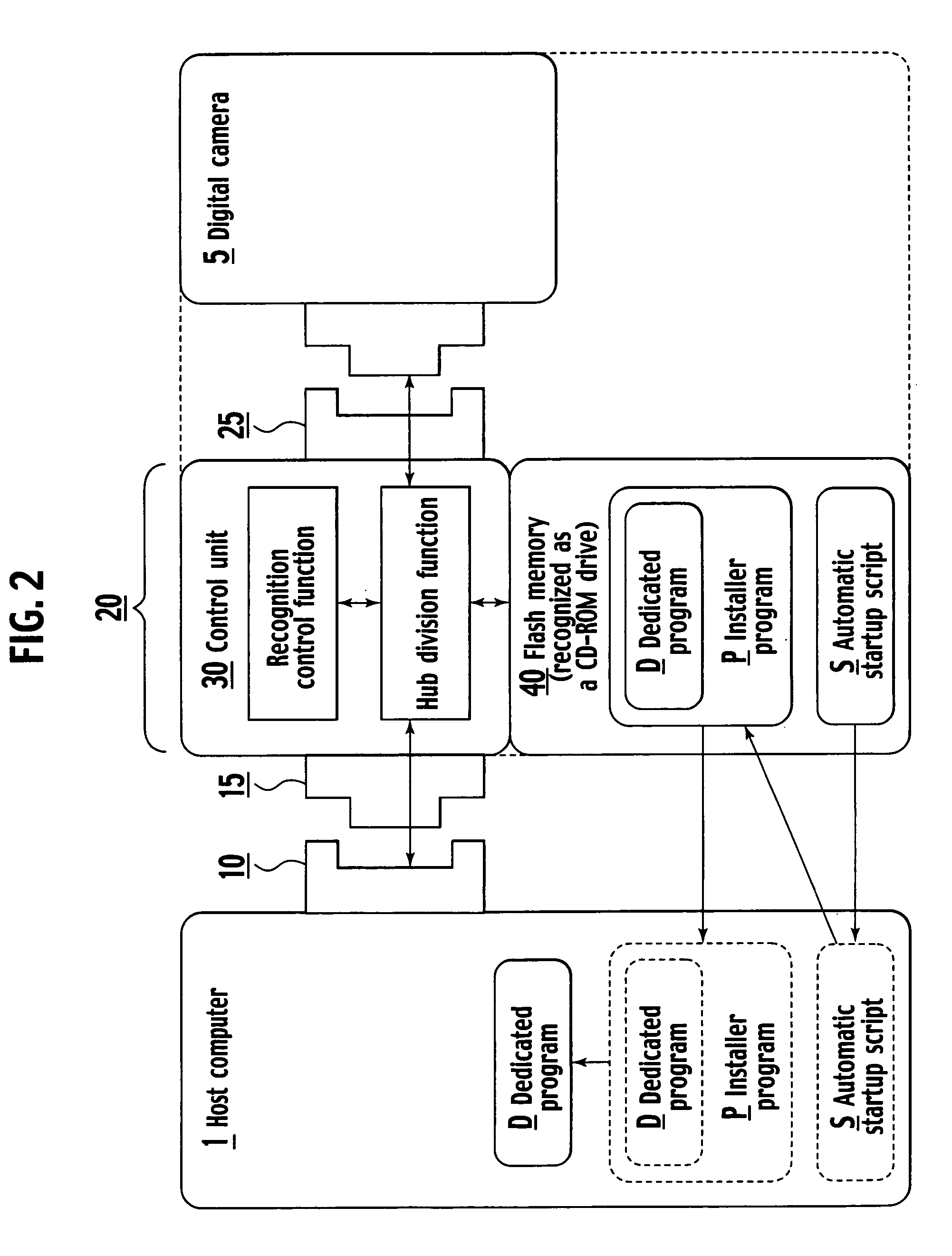
[0178] In the above-described first embodiment, a plurality of devices were handled using hub division, causing respective devices to be recognized by the computer 1 with a certain time difference. The following second embodiment can be implemented by partially modifying it. Here, FIG. 2 illustrates the configuration of second embodiment in simplified form.

[0179] Namely, second embodiment is a removable device 20 including a male connector 15 used for attaching the device to a USB port 10 of a computer 1, which executes an automatic startup script stored in the device upon connection of the CD-ROM, a control unit 30, which operates as control means, and a flash memory 40 operating as its main storage device, and including a USB port 25 (female connector) to which another peripheral device (herein, digital camera 5) is connected.

[0180] In addition, the control unit 30 has a function (hub division function) for setting up all or part of the flash memory 40...

third embodiment

[0194] 6. Third Embodiment

[0195] In the removable devices 2 and 20 of the above-described first and second embodiments, the control units 3 and 30 play an important role. Third embodiment gives an example of a removable device 200 (called “the present device” below), which is imparted with functions from both removable devices 2 and 20 and which provides an additional specific embodiment of this control unit. In addition, even better effects in terms of convenience and security are obtained by appropriately combining the various functions described in first to third embodiments.

[0196] 6-1. Hardware Configuration

[0197] First of all, an example of the hardware configuration of the present device 200 is illustrated in FIG. 3. Namely, a USB microcomputer 300, such as a RISC microcomputer, acts as a control unit, providing hub functionality according to its firmware 310 in the same manner as control units 3 and 30 in first and second embodiments. In addition, the present device 200 is ...


PUM


Abstract

The present invention provides a highly convenient removable device and a startup method. A hub division unit 31 in a single composite device 2 allocates data exchange with the computer 1 side to a plurality of devices, thereby easily realizing a plurality of functions. When connected to a USB, a recognition control unit 32 returns a signal representing a CD-ROM in a simulated manner in response to inquiry about the type of the device from the host side. When a device is mounted, a desired processing such as a program execution described in the script is automatically performed without installing a resident program for detecting a device mounting in advance in the computer side.

Description

BACKGROUND OF THE INVENTION [0001] 1. Field of the Invention [0002] The present invention relates to a removable device and a log-in method capable of producing superior advertising effects and offering superior convenience and security. [0003] 2. Description of the Background Art [0004] Along with the continued growth in the use of various computers, such as personal computers (PCs), which accompanies the increasing use and progress in semiconductor technology and the Internet, recent years have seen diversification in the methods used for connecting peripheral devices. As a result, a need has been created for a universal peripheral device interface that can be used for any personal computer models and the USB (Universal Serial Bus) interface has been proposed as a specific example of such a standard. Moreover, reductions in the weight and size of various computers and the expansion of their portable (mobile) uses have created a need for removable external storage devices, fueling ...

Claims


Application Information

Patent Timeline
IPC IPC(8): G06F15/177G06F3/00G06F12/14G06F13/00G06F13/10
CPCG06F8/60G06F9/4411G06F21/79G06F21/85G06F2221/2139G06F2221/2143
Inventor KOBAYASHI, SHINYAUEMATSU, SHINJI
Owner SASLITE CORP
Learn More