Driving device and device method

a technology of driving device and device method, which is applied in the direction of instruments, computing, electric digital data processing, etc., can solve the problems of poor sensing situation, further affecting the detection accuracy of touch points, etc., and achieve the effect of improving the signal-to-noise ratio (snr)

Active Publication Date: 2019-11-12
HANNSTAR DISPLAY CORPORATION
View PDF14 Cites 3 Cited by
  • Summary
  • Abstract
  • Description
  • Claims
  • Application Information

AI Technical Summary

Benefits of technology

[0006]The disclosure is directed to a driving device and a driving method, where a plurality of Walsh codes is obtained from a Walsh matrix to serve as driving signals to drive a sensing device, by which a noise interference of signals on a transmission path of the sensing device is effectively eliminated or decreased, so as to improve a signal to noise ratio (SNR) of a readout circuit for readout a sensing signal generated by the sensing device.
[0009]According to the above description, the driving device and the driving method of the disclosure may take a plurality of Walsh codes orthogonal to each other to serve as the driving signals to drive the sensing device. Therefore, the noise interference between the sensing signals generated by a sensing result of the sensing device can be effectively decreased. In this way, the signal processing circuit demodulates the sensing signals to obtain an accurate sensing result.

Problems solved by technology

In the technique of the on-cell type touch panel, the touch panel is liable to be interfered by noises of the lower panel display to cause a detection error of a touch point, especially when a thickness of a touch display panel (for example, an active matrix organic light emitting diode (AMOLED) display panel combined with a touch panel) becomes thinner and thinner, for example, to reach a level below 100 μm, an influence of upper electrodes of the AMOLED display panel on a sensing electric field is more and more obvious, such that poor sensing situation is often occurred.
Particularly, on a flexible display touch panel, due to an electrical imbalance phenomenon caused by panel bending, detection accuracy of the touch point is further affected.

Method used


Image

  • Driving device and device method
  • Driving device and device method
  • Driving device and device method

Examples


Embodiment Construction

[0021]A plurality of embodiments is provided below to describe the disclosure, though the disclosure is not limited to the provided embodiments, and the provided embodiments can be suitably combined. A term “couple” used in the full text of the disclosure (including the claims) refers to any direct and indirect connections. For example, if a first device is described to be coupled to a second device, it is interpreted as that the first device is directly coupled to the second device, or the first device is indirectly coupled to the second device through other devices or connection means. Moreover, a term “signal” refers to at least a current, a voltage, a charge, a temperature, data, an electromagnetic wave or any other one or more signals.

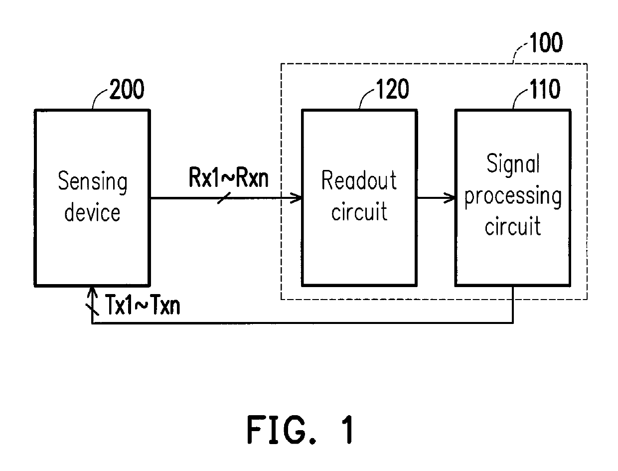
[0022]FIG. 1 is a schematic diagram of a driving device according to an embodiment of the disclosure. Referring to FIG. 1, the driving device 100 includes a signal processing circuit 110 and a readout circuit 120. In the present embodiment, the dr...


PUM


Abstract

The present disclosure provides a driving device for driving a sensing device having a plurality of driving electrodes and a plurality of sensing electrodes. The driving device includes a signal processing circuit and a readout circuit. The signal processing circuit is electrically connected to the plurality of driving electrodes of the sensing device. The signal processing circuit is configured to generate a plurality of driving signal to drive the sensing device. The signal processing circuit selects a plurality of Walsh codes from a plurality of rows or columns of a Walsh matrix to serve as a plurality of driving signals. The readout circuit readouts the sensing device to generate a plurality of sensing signals and provides the plurality of sensing signals to the signal processing circuit, so that the signal processing circuit demodulates the plurality of sensing signals. In addition, a driving method is also provided.

Description

CROSS-REFERENCE TO RELATED APPLICATION[0001]This application claims the priority benefit of Taiwan application serial no. 105143503, filed on Dec. 28, 2016. The entirety of the above-mentioned patent application is hereby incorporated by reference herein and made a part of this specification.BACKGROUND OF THE DISCLOSUREField of the Disclosure[0002]The disclosure relates to a driving technique, and particularly relates to a driving device used for driving a sensing device and a driving method.Description of Related Art[0003]Along with development of technology, electronic products have become necessary tools in people's life. In order to provide a user-friendly user interface, it is a necessary trend to provide a touch display panel with a touch function to the electronic products.[0004]In today's technical field, the touch panels are divided into plug-in type and non-plug-in type touch panels, where the non-plug-in type touch panels can be divided into on-cell type and in-cell type ...

Claims


Application Information

Patent Timeline
Patent Type & Authority Patents(United States)
IPC IPC(8): G06F3/041G06F3/044
CPCG06F3/0412G06F3/0418G06F3/044G06F2203/04102G06F3/04166
Inventor LU, YI-CHUANCHEN, HENG-YINCHAO, CHANG-POLUO, GUAN-JUNG
Owner HANNSTAR DISPLAY CORPORATION
Why Eureka
Try Eureka