Inner-rotor motor and rotor thereof

a technology of inner-rotor motor and rotor, which is applied in the direction of dynamo-electric components, dynamo-electric machines, magnetic circuit shapes/forms/construction, etc., can solve the problems of increasing the complexity of production procedures, noise or vibration generation, and insufficient bonding effect between the inner-rotor motor and the rotor, so as to reduce noise or vibration generated during the rotation of the inner-rotor motor, the coupling effect between the plurality of permanen

Active Publication Date: 2019-11-12
SUNONWEALTH ELECTRIC MACHINE IND
View PDF18 Cites 0 Cited by
  • Summary
  • Abstract
  • Description
  • Claims
  • Application Information

AI Technical Summary

Benefits of technology

[0009]It is therefore the objective of this invention to provide an inner-rotor motor and a rotor of the inner-rotor motor, in which a limiting member is provided to cover and fix a plurality of permanent magnets of the rotor in the receiving portions of the iron core. As such, the bonding effect between the plurality of permanent magnets and the iron core can be reinforced.
[0031]The inner-rotor motor and the rotor of the motor are able to prevent the plurality of permanent magnets from disengaging from the receiving portions during the rotation of the rotor by covering the plurality of permanent magnets with one or more limiting members arranged at one or two sides of the iron core in the axle direction of the shaft. As such, the noise or vibration generated during the rotation of the inner-rotor motor can be reduced. Furthermore, in the structures of the inner-rotor motor and the rotor of the motor, the coupling effect between the plurality of permanent magnets and the iron core can be reinforced by simply coupling the one or more limiting members with the shaft without applying the adhesive between the plurality of permanent magnets and the magnetic yoke portion. Thus, the production procedure of the rotor of the inner-rotor motor is simplified. Besides, the bonding effect between the plurality of permanent magnets and the iron core does not degrade after a long term of use of the rotor, thus prolonging the service life of the rotor of the inner-rotor motor.

Problems solved by technology

However, there exists a gap 94 between the tubular connection portion 921 and the permanent magnet 93, leading to an insufficient bonding effect between the iron core 92 and the permanent magnet 93.
Thus, the rotor 9 is unbalanced during the rotation thereof, leading to the generation of noise or vibration.
However, the use of the adhesive will increase the complexity of the production procedure.
Moreover, the permanent magnet 93 needs to bear a radially outward inertia force during the rotation of the rotor 9, leading to the deterioration or disengagement of the adhesive after a long term of use.

Method used


Image

  • Inner-rotor motor and rotor thereof
  • Inner-rotor motor and rotor thereof
  • Inner-rotor motor and rotor thereof

Examples


Embodiment Construction

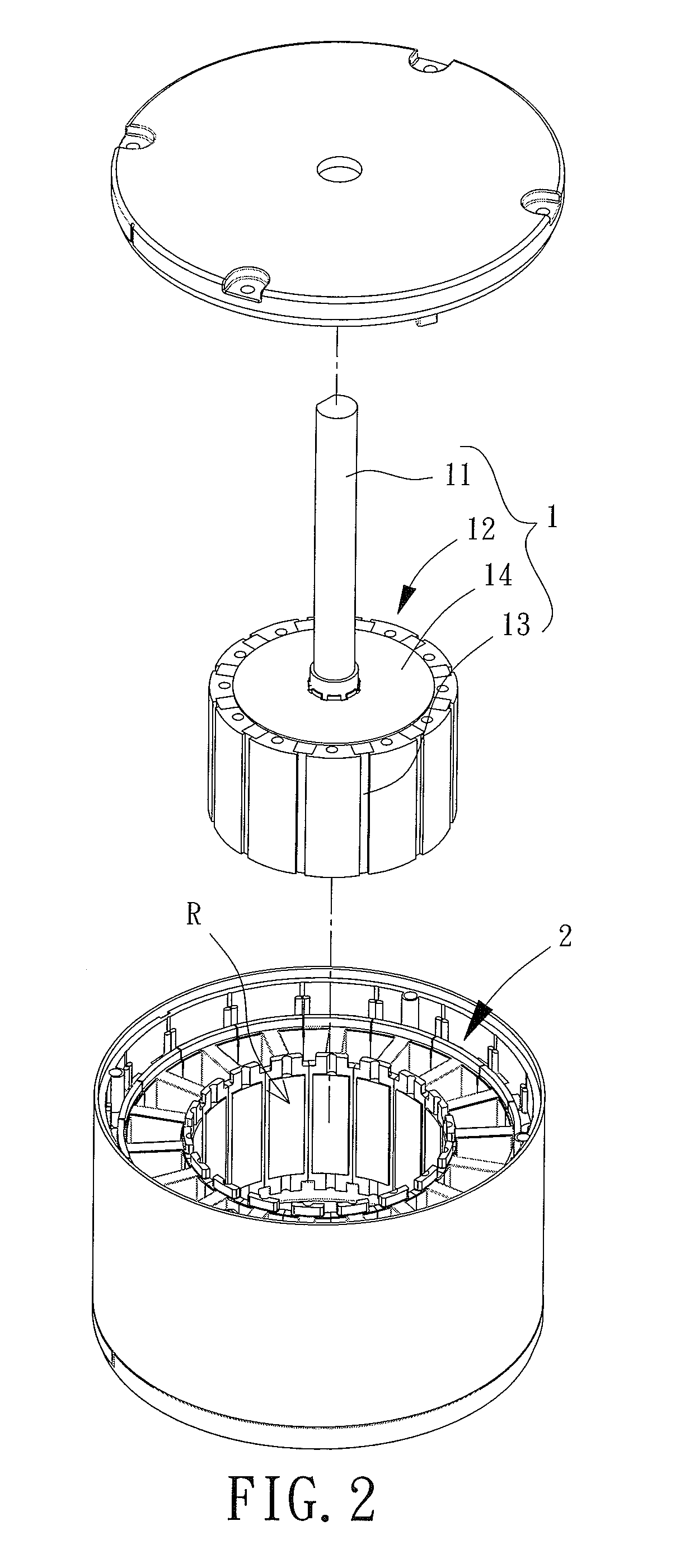
[0047]FIG. 2 is an exploded view of an inner-rotor motor according to a first embodiment of the invention. The inner-rotor motor includes a rotor 1 and a stator 2. The rotor 1 is rotatably coupled with the stator 2.

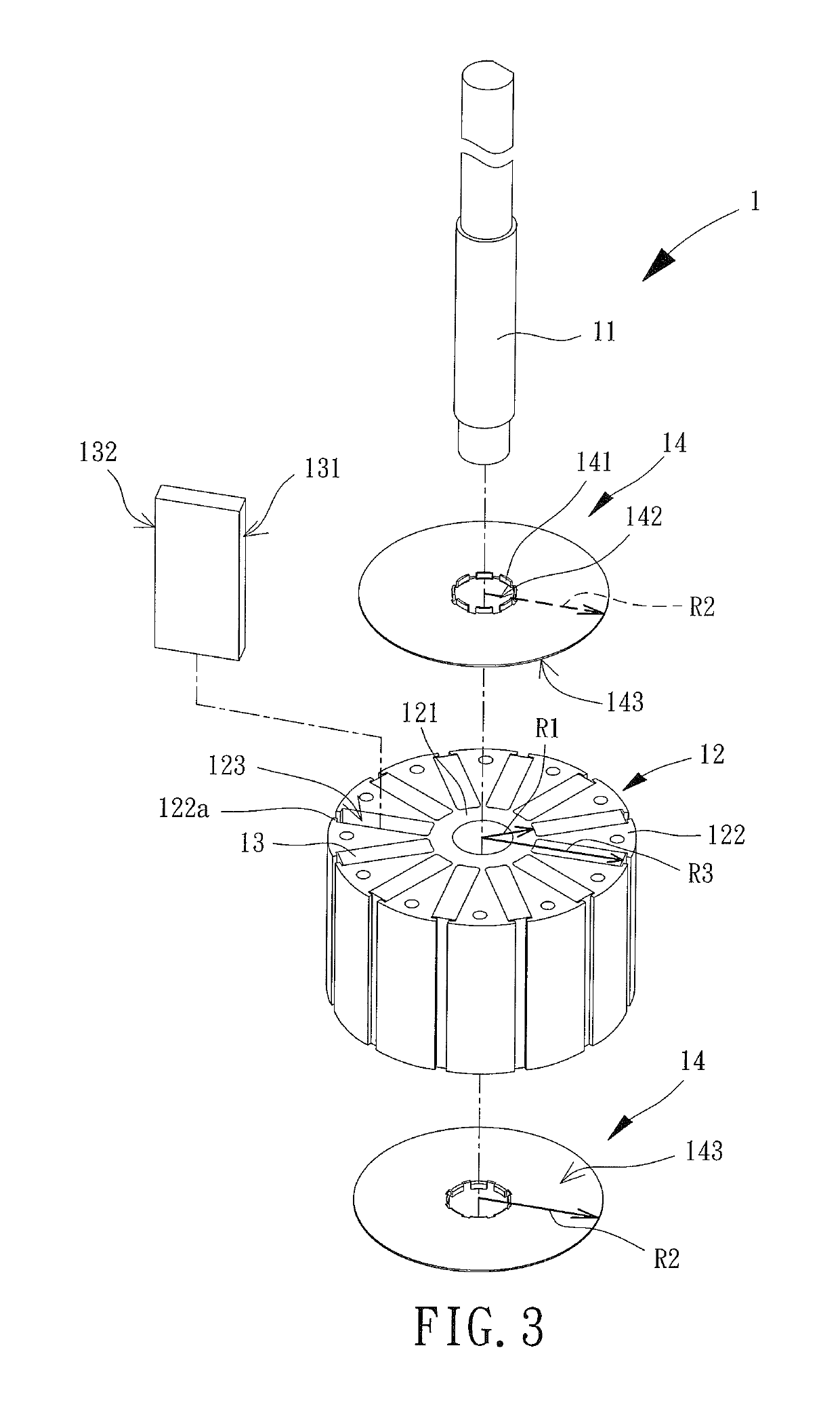
[0048]FIG. 3 is an exploded view of the rotor 1. The rotor 1 includes a shaft 11, an iron core 12, a plurality of permanent magnets 13 and at least one limiting member 14. The iron core 12 and the at least one limiting member 14 are coupled with the shaft 11. The plurality of permanent magnets 13 is mounted to the iron core 12. The stator 2 (shown in FIG. 2) is in an enclosed form having a compartment “R.” The iron core 12 and the plurality of permanent magnets 13 are received in the compartment “R.” The shaft 11 is rotatably coupled with the stator 2.

[0049]The iron core 12 is made of magnetically conductive material. For example, the iron core 12 may be in the form of a plurality of stacked silicon steel plates, or may be in the form of a monolithic piece made of magneti...


PUM


Abstract

An inner-rotor motor and a rotor of the inner-rotor motor reduce noise or vibration generated during the rotation of the motor. The rotor includes a shaft, an iron core, a plurality of permanent magnets and a limiting member. The iron core includes a magnetic yoke portion coupled with an outer periphery of the shaft, as well as a plurality of magnetic pole portions circumferentially coupled with an outer periphery of the magnetic yoke portion. The iron core forms a plurality of receiving portions, and each receiving portion is formed between two adjacent magnetic pole portions. The permanent magnets are received in the receiving portions, respectively. The limiting member is arranged at one side of the iron core, and includes a covering face covering the permanent magnets in the axle direction of the shaft.

Description

CROSS REFERENCE TO RELATED APPLICATIONS[0001]The application claims the benefit of Taiwan application serial No. 104134060, filed on Oct. 16, 2015, and the subject matter of which is incorporated herein by reference.BACKGROUND OF THE INVENTION[0002]1. Field of the Invention[0003]The present invention generally relates to an inner-rotor motor and a rotor of the inner-rotor motor and, more particularly, to a rotor having an iron core and an inner-rotor motor using the rotor.[0004]2. Description of the Related Art[0005]FIG. 1 shows a rotor 9 of a conventional inner-rotor motor. The rotor 9 includes a shaft 91, an iron core 92 and a plurality of permanent magnets 93. The iron core 92 includes a tubular connection portion 921 fitted around the shaft 91. The tubular connection portion 921 is connected to a plurality of magnetic pole portions 922. The quantities of the plurality of magnetic pole portions 922 and the plurality of permanent magnets 93 correspond to the quantity of the magnet...

Claims


Application Information

Patent Timeline
Patent Type & Authority Patents(United States)
IPC IPC(8): H02K1/27H02K7/00
CPCH02K7/003H02K1/2706H02K1/2773
Inventor HORNG, ALEXWANG, CHI-MINLIU, KU-LING
Owner SUNONWEALTH ELECTRIC MACHINE IND
Why Eureka
Try Eureka