Restricted capacitor switching

a capacitor switching and restriction technology, applied in the direction of electrical discharge tubes, multiple-port networks, electrical apparatus, etc., can solve the problems of device shrinkage, failure, and complex structur

Active Publication Date: 2019-11-19
ASM AMERICA INC
View PDF190 Cites 44 Cited by
  • Summary
  • Abstract
  • Description
  • Claims
  • Application Information

AI Technical Summary

Benefits of technology

[0007]The present disclosure may be directed, in one aspect, to an impedance matching network, the network comprising a radio frequency (RF) input configured to operably couple to an RF source; an RF output configured to operably couple to a plasma chamber; a first electronically variable capacitor (EVC) comprising discrete capacitors configured to be switched in and out to alter a first capacitance of the first EVC; a second EVC comprising discrete capacitors configured to be switched in and out to alter a second capacitance of the second EVC; and a control circuit operably coupled to the first and second EVCs, the control circuit configured to determine or receive a reflection parameter value at the RF input or the RF output; stop the altering of the first capacitance and the second capacitance when the reflection parameter value is at or below a first reflection value; cause a limited altering of the first capacitance and the second capacitance to pursue an impedance match when the reflection parameter value is (a) at or above a second reflection value and (b) at or below the third reflection value, the limited altering allowing only a predetermined number of predetermined discrete capacitors to switch in or out; and cause an unlimited altering of the first capacitance and the second capacitance to pursue an impedance match when the reflection parameter value is at or above a third reflection value, the unlimited altering allowing any discrete capacitor of the first or second EVC to switch in or out.
[0008]In another aspect, the present disclosure may be directed to a method of matching an impedance comprising operably coupling a radio frequency (RF) input of a matching network to an RF source; operably coupling an RF output of the matching network to a plasma chamber, the plasma chamber comprising (a) a first electronically variable capacitor (EVC) comprising discrete capacitors configured to be switched in and out to alter a first capacitance of the first EVC, and (b) a second EVC comprising discrete capacitors configured to be switched in and out to alter a second capacitance of the second EVC; and determining or receiving a reflection parameter value at the RF input or the RF output; stopping the altering of the first capacitance and the second capacitance when the reflection parameter value is at or below a first reflection value; causing a limited altering of the first capacitance and the second capacitance to pursue an impedance match when the reflection parameter value is (a) at or above a second reflection value and (b) at or below the third reflection value, the limited altering allowing only a predetermined number of predetermined discrete capacitors to switch in or out; and causing an unlimited altering of the first capacitance and the second capacitance to pursue an impedance match when the reflection parameter value is at or above a third reflection value, the unlimited altering allowing any discrete capacitor of the first or second EVC to switch in or out.
[0009]In another aspect, the present disclosure may be directed to a semiconductor processing tool comprising a plasma chamber configured to deposit a material onto a substrate or etch a material from the substrate; and an impedance matching network operably coupled to the plasma chamber, the matching network comprising a radio frequency (RF) input configured to operably couple to an RF source; an RF output configured to operably couple to the plasma chamber; a first electronically variable capacitor (EVC) comprising discrete capacitors configured to be switched in and out to alter a first capacitance of the first EVC; a second EVC comprising discrete capacitors configured to be switched in and out to alter a second capacitance of the second EVC; and a control circuit operably coupled to the first and second EVCs, the control circuit configured to determine or receive a reflection parameter value at the RF input or the RF output; stop the altering of the first capacitance and the second capacitance when the reflection parameter value is at or below a first reflection value; cause a limited altering of the first capacitance and the second capacitance to pursue an impedance match when the reflection parameter value is (a) at or above a second reflection value and (b) at or below the third reflection value, the limited altering allowing only a predetermined number of predetermined discrete capacitors to switch in or out; and cause an unlimited altering of the first capacitance and the second capacitance to pursue an impedance match when the reflection parameter value is at or above a third reflection value, the unlimited altering allowing any discrete capacitor of the first or second EVC to switch in or out.
[0010]In another aspect, the present disclosure may be directed to a method of manufacturing a semiconductor, the method comprising placing a substrate in a plasma chamber configured to deposit a material layer onto the substrate or etch a material layer from the substrate; and coupling an impedance matching circuit between a radio frequency (RF) source and the plasma chamber, the impedance matching circuit comprising a radio frequency (RF) input configured to operably couple to an RF source; an RF output configured to operably couple to a plasma chamber; a first electronically variable capacitor (EVC) comprising discrete capacitors configured to be switched in and out to alter a first capacitance of the first EVC; a second EVC comprising discrete capacitors configured to be switched in and out to alter a second capacitance of the second EVC; and a control circuit operably coupled to the first and second EVCs, the control circuit configured to determine or receive a reflection parameter value at the RF input or the RF output; stop the altering of the first capacitance and the second capacitance when the reflection parameter value is at or below a first reflection value; cause a limited altering of the first capacitance and the second capacitance to pursue an impedance match when the reflection parameter value is (a) at or above a second reflection value and (b) at or below the third reflection value, the limited altering allowing only a predetermined number of predetermined discrete capacitors to switch in or out; and cause an unlimited altering of the first capacitance and the second capacitance to pursue an impedance match when the reflection parameter value is at or above a third reflection value, the unlimited altering allowing any discrete capacitor of the first or second EVC to switch in or out.

Problems solved by technology

In complex semiconductor processes, where the impedance changes are very rapid, the rapid and frequent movements put stresses on the VVC leading to their failures.
As semiconductor devices shrink in size and become more complex, however, the feature geometries become very small.
Current RF matching networks take 1-2 seconds to tune the process and this results in unstable process parameters for a significant portion of the process time.

Method used


Image

  • Restricted capacitor switching
  • Restricted capacitor switching
  • Restricted capacitor switching

Examples


Embodiment Construction

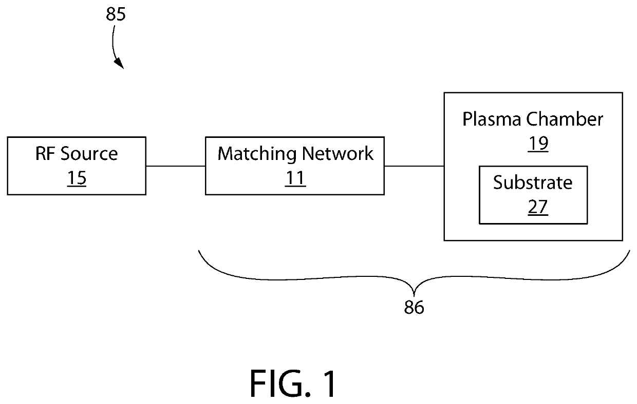
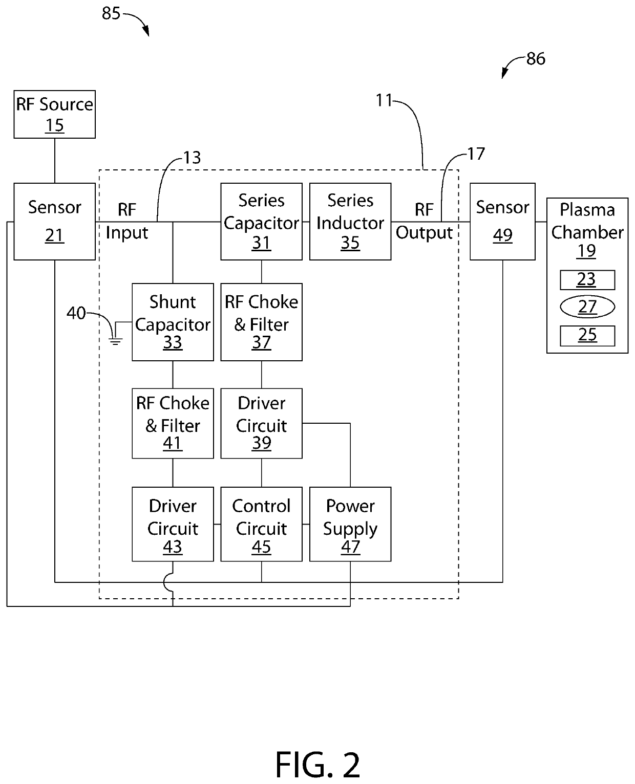
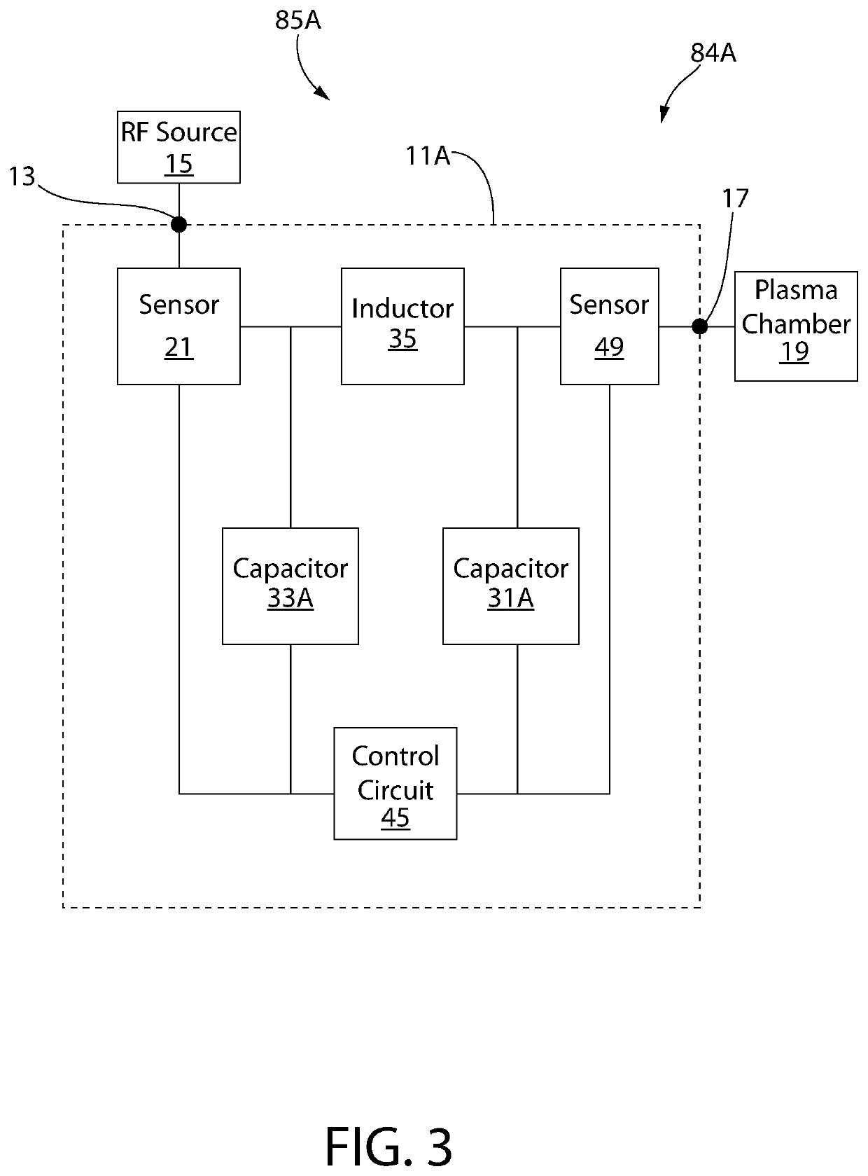
[0021]The following description of the preferred embodiment(s) is merely exemplary in nature and is in no way intended to limit the invention or inventions. The description of illustrative embodiments is intended to be read in connection with the accompanying drawings, which are to be considered part of the entire written description. In the description of the exemplary embodiments disclosed herein, any reference to direction or orientation is merely intended for convenience of description and is not intended in any way to limit the scope of the present inventions. The discussion herein describes and illustrates some possible non-limiting combinations of features that may exist alone or in other combinations of features. Furthermore, as used herein, the term “or” is to be interpreted as a logical operator that results in true whenever one or more of its operands are true. Furthermore, as used herein, the phrase “based on” is to be interpreted as meaning “based at least in part on,” ...


PUM


Abstract

In one embodiment, the present disclosure is directed to a method for matching an impedance. The method can include determining or receiving a reflection parameter value at an RF input or output; stopping the altering of a first capacitance and a second capacitance when the reflection parameter value is at or below a first reflection value; causing a limited altering of the first capacitance and the second capacitance to pursue an impedance match when the reflection parameter value is at or above a second reflection value and at or below the third reflection value; and causing an unlimited altering of the first capacitance and the second capacitance to pursue an impedance match when the reflection parameter value is at or above a third reflection value.

Description

CROSS REFERENCE TO RELATED APPLICATIONS[0001]The present application claims the benefit of U.S. Provisional Patent Application No. 62 / 530,446, filed Jul. 10, 2017, which is incorporated herein by reference.BACKGROUND[0002]The semiconductor device fabrication process uses plasma processing at different stages of fabrication to make a semiconductor device such as a microprocessor, a memory chip, or another integrated circuit or device. Plasma processing involves energizing a gas mixture by imparting energy to the gas molecules by the introduction of RF (radio frequency) energy into the gas mixture. This gas mixture is typically contained in a vacuum chamber, also called a plasma chamber, and the RF energy is introduced through electrodes or other means in the chamber. In a typical plasma process, the RF generator generates power at the desired RF frequency and power, and this power is transmitted through the RF cables and networks to the plasma chamber.[0003]To provide efficient trans...

Claims


Application Information

Patent Timeline
Patent Type & Authority Patents(United States)
IPC IPC(8): H03H7/38H01J37/32H03H11/28H03H7/40H01L21/67
CPCH03H11/28H03H7/40H01J37/32183H01J2237/332H01L21/67069H01J2237/334H01J2237/24564
Inventor BHUTTA, IMRAN AHMEDLOZIC, TOMISLAV
Owner ASM AMERICA INC
Why Eureka
Try Eureka