
Dry, low-NOx combustor with integrated thermoelectric generator

a combustor and thermoelectric generator technology, applied in the manufacture/treatment of thermoelectric devices, electrical apparatus, borehole/well accessories, etc., can solve the problems of major gas leakage sources, significant methane emissions, etc., and achieve the effect of reducing gas temperature, constant heat flux, and compact structur

Active Publication Date: 2019-11-26
GAS TECH INST
View PDF15 Cites 0 Cited by
  • Summary
  • Abstract
  • Description
  • Claims
  • Application Information

AI Technical Summary

Benefits of technology

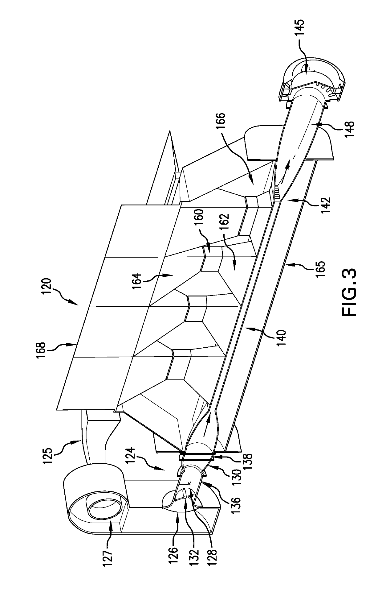
[0006]The invention provides an efficient, compact, and reliable apparatus and method for producing power thermoelectrically from, for example, natural gas or other gaseous hydrocarbon feedstocks. Embodiments of the invention utilize a pre-mixed oxidant and fuel stream at a mixture ratio that provides a combustion temperature below the thermal NOx formation temperature and at the nominal operating temperature(s) of the thermoelectric devices. The pre-mix portion of the system is desirably isolated from the combustor via a flame arrestor device which prevents the flame from traveling back to the pre-mix section. Once combustion is complete, the hot gases are routed to a series of thermoelectric modules and / or couples desirably arrayed both radially and / or axially along the length of the combustor. Each thermoelectric module absorbs a portion of the heat, thereby reducing the gas temperature. It is desirable to maintain a constant heat flux into the TEG stack. To achieve this, the heat transfer film coefficient along the length can be increased to offset the reduction in the gas temperature. The thermoelectric modules are comprised of one or more pairs of thermoelectric couples (e.g., segmented) with the thermoelectric materials in each couple selected for the hot and cold side temperatures. Once the gases pass the last row of thermoelectric modules, the remaining heat in the gases can be recovered via a heat exchanger to preheat the incoming combustion air. An alternate configuration for a relatively constant temperature TEG would require a heat exchange to preheat the incoming combustion air to maintain high system efficiencies.
[0007]The invention further includes a method and device for providing remote or portable power. In embodiments of this invention, the device and its power output is used primarily for powering and operating a pneumatic device. The method of operating the pneumatic device according to embodiments of this invention includes: providing a fuel to a combustor; directing heated gases from the combustor a plurality of thermoelectric couples and / or modules; and powering an air compressor with the thermoelectric couples and / or modules to operate the pneumatic device. The TEG portable power system for this method can include a dry low-NOx (DLN) burner-driven TEG such as described above and herein, an air compressor, and any necessary power electronics. The air compressor according to some preferred embodiments of this invention is a DC-driven air compressor, thus eliminating the need for a DC inverter.
[0008]The heat for the TEG is provided by a small low NOx combustor to provide power (e.g., ˜25 We) for remote gas and oil wellhead instrument air or other suitable power needs. The invention provides an instrument air system that is sufficiently low-cost to enable rapid adoption by the oil and gas industry for the retrofit of existing natural gas powered pneumatic devices. The apparatus and method of this invention enables operating pneumatic devices with air and eliminates gas emissions while providing an economically attractive and secure alternative. Current system evaluations indicate only 1 / 225th the amount of natural gas is used by the proposed system (based on average emissions per EPA 430-R-15-004) to generate the 25 We power commonly required for the instrument air to operate the pneumatic devices. Additionally, this small portion of natural gas is combusted, thus releasing carbon dioxide. Assuming the long-term GHG impact ratio of 28:1, this concept reduces GHG emissions from this source by three orders of magnitude, which translates to a 13-25% reduction in U.S. natural gas emissions from this source.
[0009]In addition to reducing GHG emissions, the proposed system has several unique attributes: (1) simple, reliable, and low-cost for retrofitting into numerous gas wells operating in the U.S.; (2) scalable to lower power (e.g., 25 We) as required for a majority of gas well operations, (3) reliable and robust unattended operation in widely distributed and remote areas; (4) secure profile for deployment that is less prone to theft at these remote sites than other technologies; and / or (5) high efficiency and low cost that directly translates to increased recoverable revenue.

Problems solved by technology

Methane emissions are a significant issue due to the Greenhouse Gas Intensification factor and the amount of methane that is produced.
A major gas leakage source is emissions from natural gas operated pneumatic devices.

Method used


Image

  • Dry, low-NOx combustor with integrated thermoelectric generator
  • Dry, low-NOx combustor with integrated thermoelectric generator

Examples


Embodiment Construction

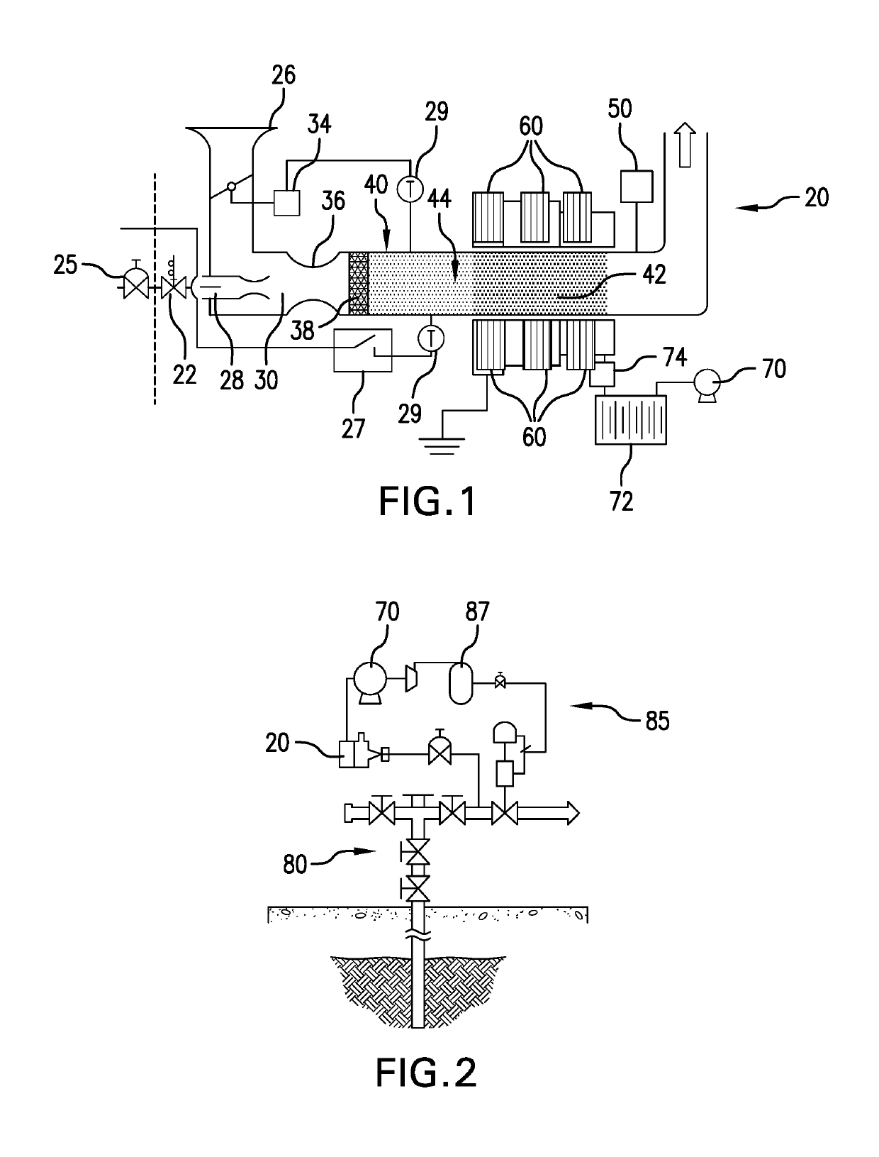
[0013]FIG. 1 schematically illustrates a thermoelectric generator (TEG) 20 for producing electrical power according to one embodiment of this invention. The TEG can be implemented for oil and gas field applications, such as shown in FIG. 2, and operated on fugitive gas to produce electrical power. The TEG apparatus provides a portable power system that can be used, without limitation for operating pneumatic devices and / or other loads.

[0014]TEG 20 is connected to a gas source 25 by any suitable connection, such as including valve 22. TEG 20 includes a burner 24 having an air inlet 26 and a gas inlet 28 both in combination with a fuel and air mixture chamber 30. The air inlet 26 is desirably filtered and can include an air damper 32, such as controlled by rotary actuator controller 34. The gas inlet 28 can be any suitable inlet mechanism, such as a jet ejector adapted to vary fuel velocity, and the gas inlet 28 can be controlled, at least in part, by a controller and a thermal switch ...


PUM


Abstract

An integrated combustor-thermoelectric generator and method for producing electrical power and / or for operating a pneumatic device. A thermoelectric generator includes a fuel and air mixture chamber with a combustor connected to the mixture chamber. The combustor including a longitudinal centerbody comprising a varying cross-sectional area along an axial length of the centerbody and a plurality of thermoelectric couples and / or modules disposed axially along sides of the centerbody. The thermoelectric generator can be paired with a DC air compressor for operating a pneumatic device by directing heated gases from the combustor to a plurality of thermoelectric couples and / or modules, and powering the air compressor with the thermoelectric couples and / or modules. The thermoelectric generator and DC compressor can be installed to a natural gas source at a well pad for operating a pneumatic device at the well pad.

Description

BACKGROUND OF THE INVENTIONField of the Invention[0001]This invention relates to power generation, and more particularly, provides a method and apparatus for generating power and pneumatic action through a thermoelectric generator device.Description of Related Art[0002]Gas and oil field operation constitutes one of the more significant sources of greenhouse gas (GHG) emissions. Methane emissions are a significant issue due to the Greenhouse Gas Intensification factor and the amount of methane that is produced. A major gas leakage source is emissions from natural gas operated pneumatic devices. Approximately 30-35% of all production related emissions in the U.S. come from pneumatic controllers. There are between 500,000 and 600,000 wells that utilize intermittent pneumatic controllers in the U.S. There is thus a continuing need for improved power and air sources for remote well head pneumatic devices.SUMMARY OF THE INVENTION[0003]This invention relates to a process and apparatus that...

Claims


Application Information

Patent Timeline
Patent Type & Authority Patents(United States)
IPC IPC(8): H01L35/30H01L35/32E21B41/00H01L35/00H01L35/34
CPCH01L35/30H01L35/32E21B41/00H01L35/34H01L35/00H10N10/13H10N10/17H10N10/00H10N10/01
Inventor MAYS, JEFFREY A.MIYATA, SHINJIROFRYE, PATRICK E.MAYS, KYLE
Owner GAS TECH INST
Learn More