
Method and apparatus for controlled transfer of fluid

a technology of fluid transfer and flow control, applied in the direction of caps, liquid handling, applications, etc., can solve the problems of not being able to have a funnel available, nor is a user at the mercy of having one availabl

Active Publication Date: 2019-12-03
VECTION LTD
View PDF32 Cites 2 Cited by
  • Summary
  • Abstract
  • Description
  • Claims
  • Application Information

AI Technical Summary

Benefits of technology

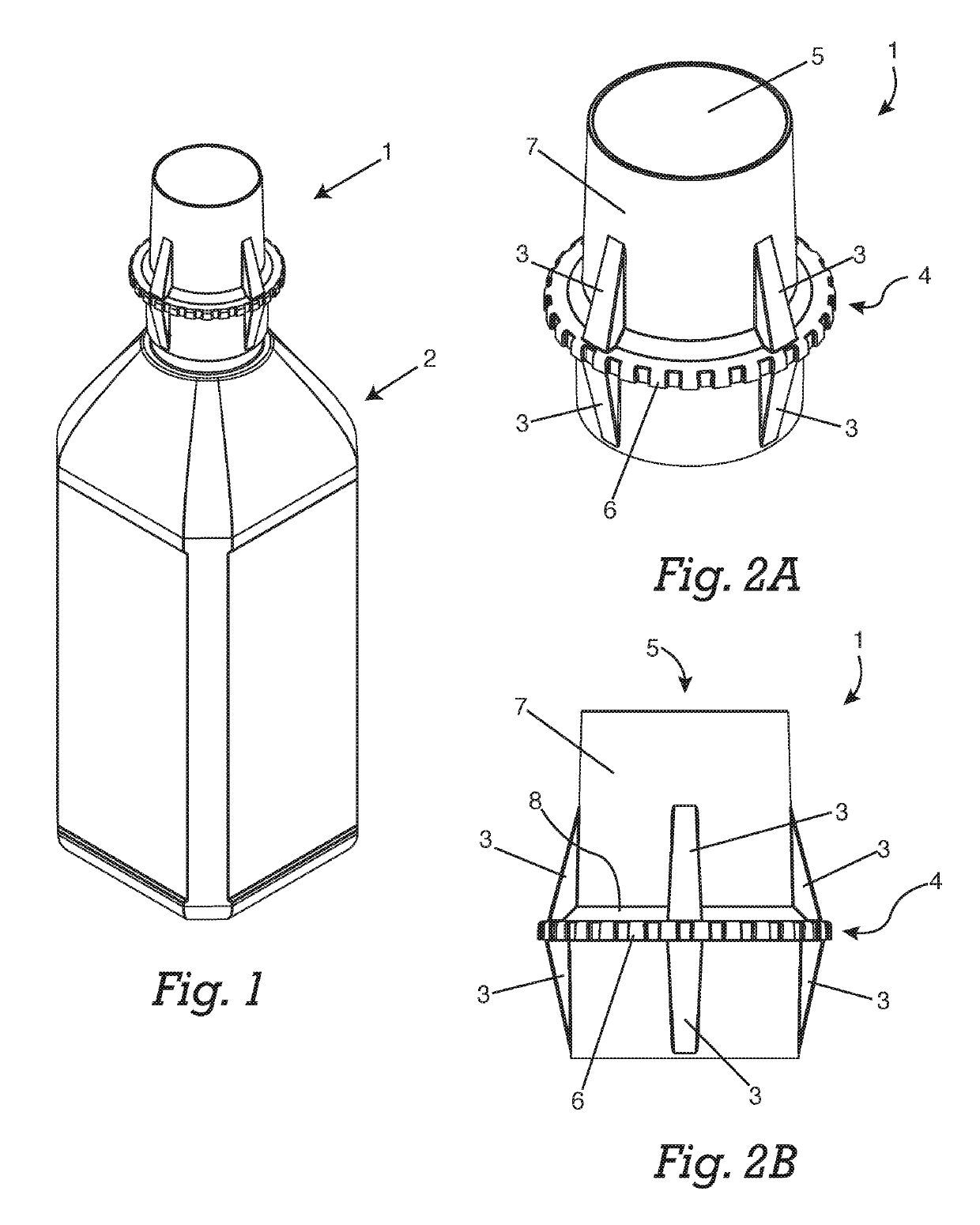
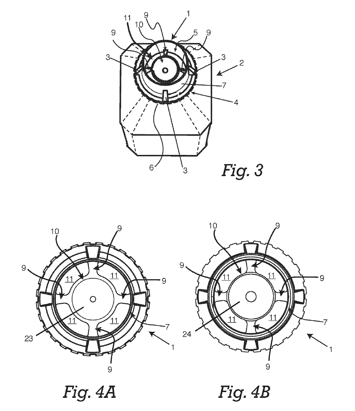
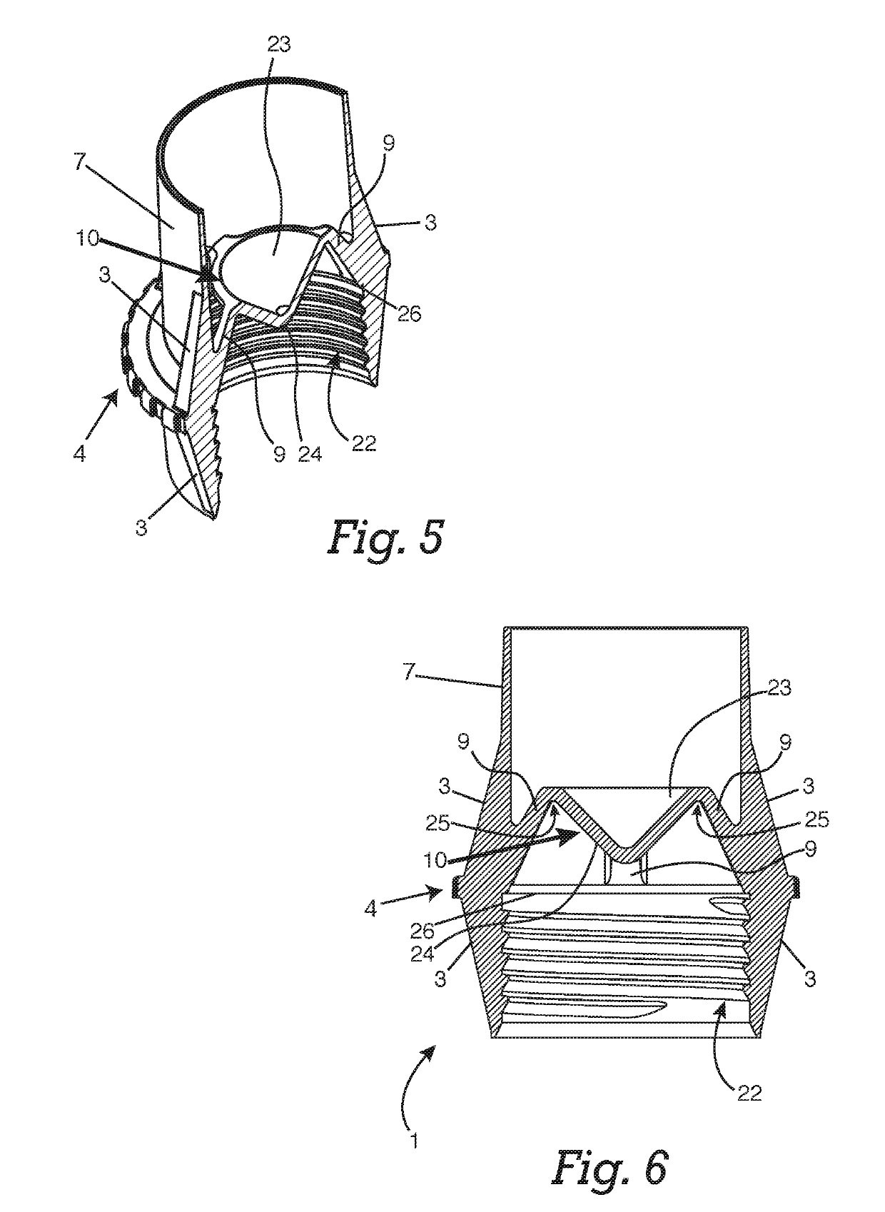
[0047]Embodiments of the present disclosure generally relate to caps, closures, seals, containers, and control of flow of fluids. Embodiments relate to improvements in the system, apparatus, and method of use of a fluid container. Certain embodiments can be used with fluids related to machinery, for instance, engine oil, brake fluid, coolant, transmission fluid, and power steering fluid. Certain embodiments of the present effectively hold and transfer a fluid or a fluid substance (referred to as a fluid), further being able to open, close, regulate flow of such fluid. The system, method, and apparatus in certain embodiments reduce messiness, leaking, uncontrolled flow of a fluid, and increase flow rate as compared to other products such as funnels. Certain embodiments of a container holding a liquid may come in many forms.
[0048]Certain embodiments of the present disclosure direct pouring of a fluid in an accurate manner. Certain embodiments transfer a fluid rapidly in a controlled manner. Certain embodiments stop the flow, start the flow, and control the flow of a liquid poured from a container. Certain embodiments allow controlled pouring of a liquid while a container is inverted. Certain embodiments allow cheap manufacturing, for instance, by using less material. Certain embodiments allow appending certain features to existing containers. Certain embodiments also enhance the user experience of dispensing fluids, and presents a more useful way of dispensing fluids in any state, such as liquid and solid. Certain embodiments eliminate the need to use a separate funnel to dispense fluids. Eliminating the need for a separate funnel means a user does not need to purchase a separate funnel. Nor is a user at the mercy of having a funnel available. A user no longer has to clean or dispose of a funnel.

Problems solved by technology

Nor is a user at the mercy of having a funnel available.

Method used


Image

  • Method and apparatus for controlled transfer of fluid
  • Method and apparatus for controlled transfer of fluid
  • Method and apparatus for controlled transfer of fluid

Examples


example

[0070]In one example case, the speed of flow of pouring motor oil through a one-pint mechanics oil funnel, or a container having a tapered head and a closure component, was tested. For this test, the assembly that included a container, a nozzle collar, and a closure component was upturned so that the nozzle collar and closure component were located at the bottom. The base of the upturned container was opened, to allow motor oil to be poured through. The closure component was in an open position.

[0071]A 315 mL volume of 10W-30 motor oil (Pennzoil), set at room temperature, was placed in a primary receptacle. The primary receptacle was instantly inverted to transfer the motor oil into a secondary receptacle, whereby a one-pint mechanics oil funnel, or a container in one embodiment of the invention was placed directly above the secondary receptacle. The amount of time to transfer the bulk of the motor oil through either the funnel or an embodiment of the invention was recorded. Transfe...


PUM


Abstract

Embodiments of the present disclosure generally relate to caps, closures, seals, and containers, and control of flow of fluids. Certain embodiments can be used with fluids related to machinery, for instance, engine oil, brake fluid, coolant, transmission fluid, and power steering fluid. Certain embodiments of the present disclosure effectively hold and transfer a fluid or a fluid substance, further being able to open, close, and regulate fluid flow. Embodiments include a single piece tubular component that includes a cap interiorly attached to such tubular component with ribs, and a container having a tapered end. In certain embodiments, a nozzle collar having a tapered end is adapted to attach to a container.

Description

CROSS REFERENCE TO REFERENCE TO RELATED APPLICATIONS[0001]This application is a continuation-in-part of U.S. patent application Ser. No. 15 / 045,075, entitled “METHOD AND APPARATUS FOR CONTROLLED TRANSFER OF FLUID”, filed Feb. 26, 2016—currently pending—the entire contents of which are incorporated herein by reference in its entirety for all purposes.FIELD OF INVENTION[0002]Embodiments of the present disclosure generally relate to caps, closures, seals, and containers, and control of flow of fluids. Certain embodiments can be used with fluids related to machinery, for instance, engine oil, brake fluid, coolant, transmission fluid, and power steering fluid. Certain embodiments of the present disclosure to effectively hold and transfer a fluid or a fluid substance (referred to as a fluid), further being able to open, close, regulate flow of such fluid. Certain embodiments include a single piece tubular component that includes a cap interiorly attached to such tubular component with rib...

Claims


Application Information

Patent Timeline
Patent Type & Authority Patents(United States)
IPC IPC(8): B65D41/04B65D47/04B65D1/02B65D47/24
CPCB65D41/0442B65D1/023B65D47/242B65D47/043B65D41/0471B65D2501/0081
Inventor MEYER, MATHEW D
Owner VECTION LTD
Learn More