
Electric power system

a technology of electric power system and electric power supply, which is applied in the direction of electric/fluid circuit, road transportation emission reduction, transportation and packaging, etc., and can solve problems that have not been fully discussed

Active Publication Date: 2019-12-03
HONDA MOTOR CO LTD
View PDF9 Cites 0 Cited by
  • Summary
  • Abstract
  • Description
  • Claims
  • Application Information

AI Technical Summary

Benefits of technology

The patent describes an electric power system that controls the charging and discharging of a battery in a device. The system uses a target value to set the desired parameters of the battery, such as voltage and temperature. The target value is determined based on the starting and ending parameters of the battery during a previous operation cycle. By setting the target value based on these parameters, the battery can be prevented from being used in a state with low battery performance. The system also determines if the battery is in a decreasing or increasing tendency, and adjusts the target value accordingly to suppress degeneration of the battery. The system can be used in vehicles and can be calibrated based on the user's usage tendency of the battery. The technical effect of the patent is to improve the performance and longevity of the battery in devices that use it.

Problems solved by technology

However, conventionally, it has not been fully discussed on what value should be set for a target charging rate, which is the target of a charging rate of the battery, within the SOC range.

Method used


Image

  • Electric power system
  • Electric power system
  • Electric power system

Examples


Embodiment Construction

[0011]In the following part, an embodiment of the disclosure is described with reference to drawings.

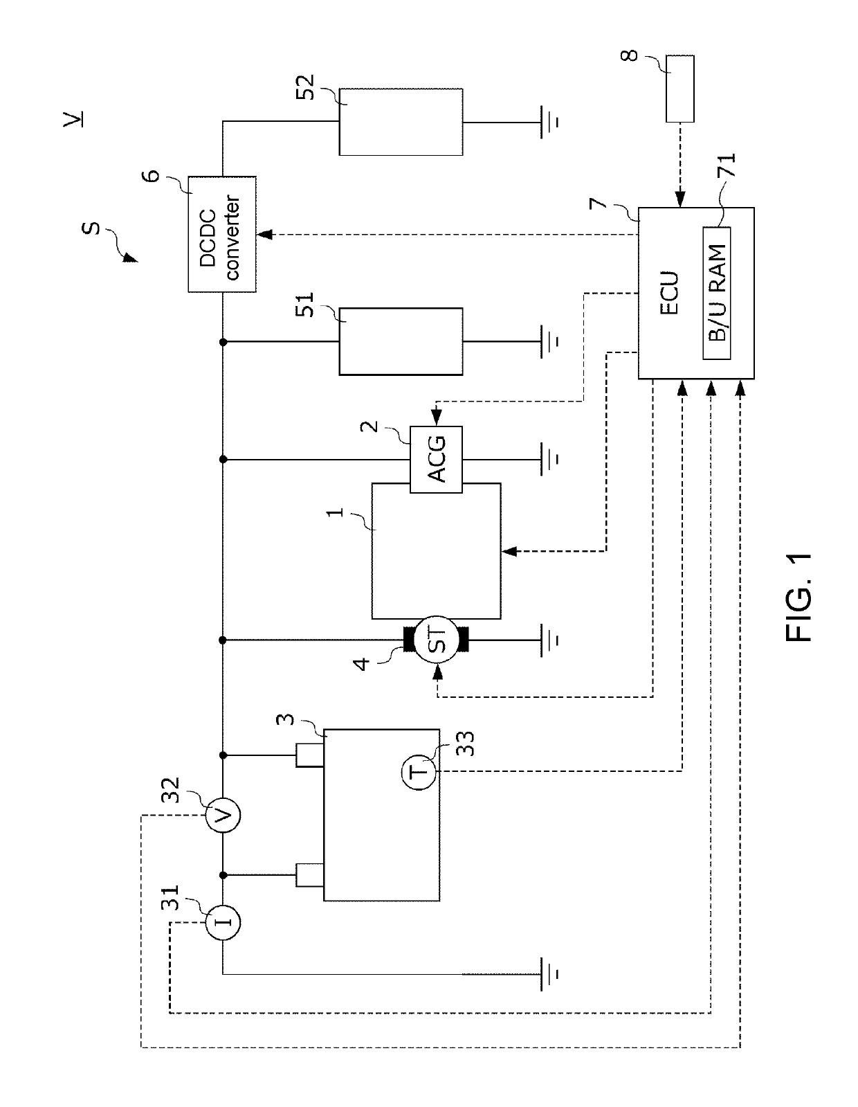
[0012]FIG. 1 is a diagram showing structures of an electric power system S of this embodiment and a vehicle V on which the electric power system S is mounted.

[0013]The electric power system S comprises an alternator 2 (referred to as “ACG 2” hereinafter), utilizing a power of an internal-combustion engine 1 (referred to as “engine 1” hereinafter) that is a power-generating source of the vehicle V to generate electric power; a battery 3, capable of being charged by an electric power generated by the ACG 2; a starter 4, starting the engine 1 using the electric power supplied from the battery 3; a first electric load 51, capable of using the electric power supplied from the battery 3 to operate; a DCDC converter 6, increasing or decreasing a voltage of the direct-current electric power of the battery 3; a second electric load 52, connected to the battery 3 via the DCDC converter 6; an E...


PUM


Abstract

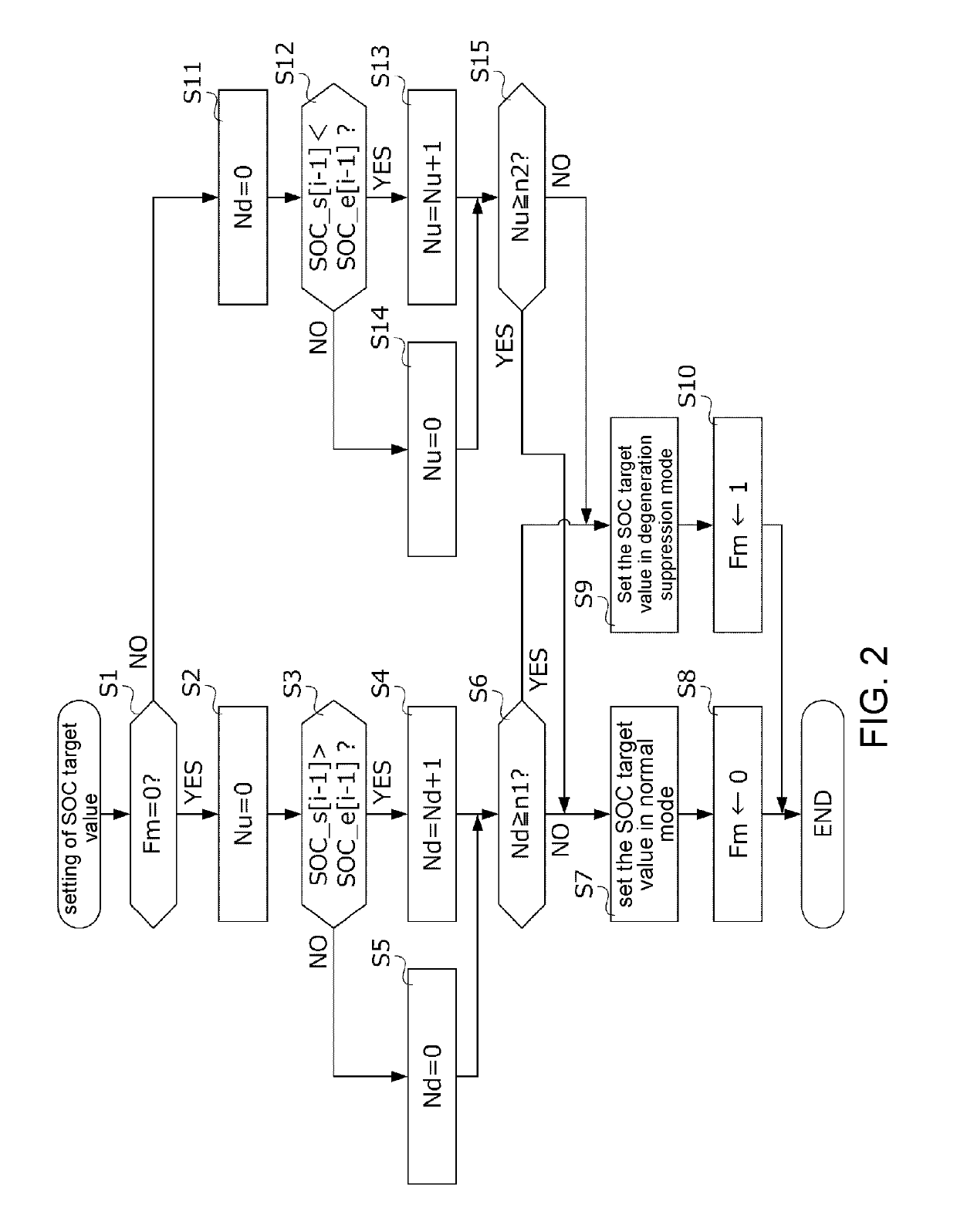
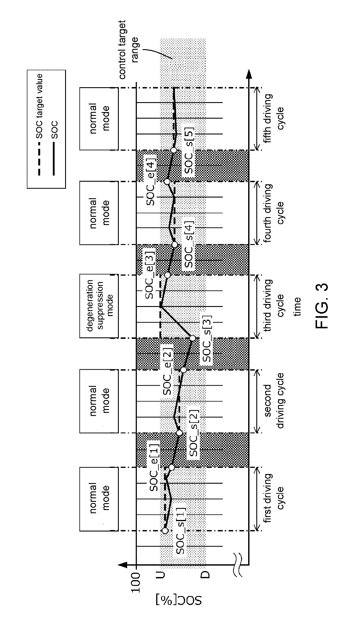
Provided is an electric power system, including: a battery, connected to an ACG and an electric load, and capable of charge by electric power generated by the ACG and discharge to the electric load; and an ECU, setting an SOC target value of the battery for each driving cycle, and controlling the charge and discharge of the battery so that the SOC of the battery becomes the SOC target value. The ECU sets the SOC target value in a normal mode when a starting SOC value in the most recent past driving cycle is lower than an ending SOC value, and sets the SOC target value in a degeneration suppression mode when the starting SOC value is greater than the ending SOC value continuously for two most recent driving cycles.

Description

CROSS-REFERENCE TO RELATED APPLICATION[0001]This application claims the priority of Japan patent application serial no. 2017-150832, filed on Aug. 3, 2017. The entirety of the above-mentioned patent application is hereby incorporated by reference herein and made a part of this specification.BACKGROUNDTechnical Field[0002]The disclosure relates to an electric power system.Description of Related Art[0003]A battery is mounted on a vehicle to supply electric power to vehicle auxiliary machines such as air conditioners, lights, and navigation systems. Besides, a power generator is mounted on the vehicle, and power of the engine for example can be utilized to drive the power generator to charge the battery properly.[0004]In patent literature 1 (Japanese Laid-open Publication No. 2016-28198), a technology is disclosed to set a usable SOC (State Of Charge) range for a charging rate of the battery (a ratio represented by percentage showing the ratio of a remaining capacity of the battery wit...

Claims


Application Information

Patent Timeline
Patent Type & Authority Patents(United States)
IPC IPC(8): H02J7/00B60R16/033
CPCH02J7/0068B60R16/033H02J7/1446H02J2310/46Y02T10/92Y02T10/70
Inventor NAMIKI, SHIGERUKOIZUMI, YUKI
Owner HONDA MOTOR CO LTD
Learn More