
Inkjet printhead and inkjet printer containing the same

a technology of inkjet printer and printhead, which is applied in the direction of printing, etc., can solve the problems of undesirable cross-talk, difficult to achieve full power closure between adjacent converters, etc., and achieve the effect of preventing cross-talk, preventing pressure waves, and preventing stretching of the chamber

Inactive Publication Date: 2006-12-07
OCE TECH
View PDF3 Cites 0 Cited by
  • Summary
  • Abstract
  • Description
  • Claims
  • Application Information

AI Technical Summary

Benefits of technology

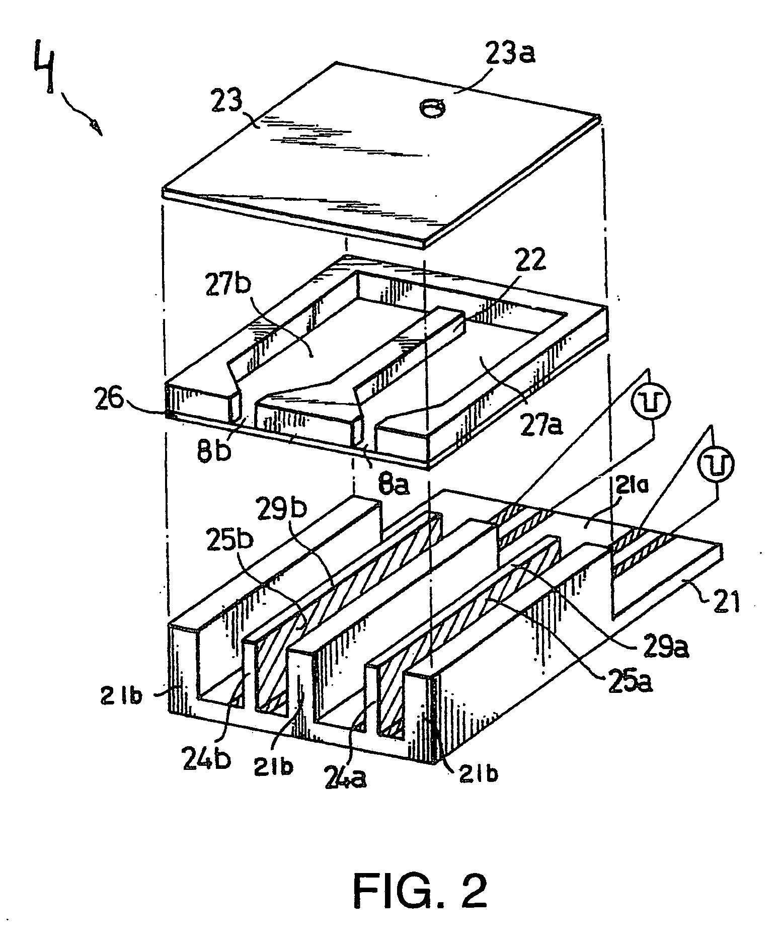
[0006] This invention is based on the recognition that it will often not be possible to prevent actuation of a converter to produce a volume change in an adjacent chamber. This is because it is difficult to both achieve a full power closure between adjacent converters and prevent stretching of the chambers. The invention now comprises a deformable wall between the chambers, the above-mentioned volume change, in essence, being fully compensated due to said deformation. In the event of an increase in pressure in the first chamber, for example, the volume in the adjacent chamber may suddenly increase due to local stretching of the chambers. This volume change may be fully compensated by bending the wall towards this adjacent chamber. This bending is induced by the sudden pressure increase in the first chamber and may be tuned by the correct choice of assembly and placing of the wall. If, for example, strong deformation is desired, a very thin wall of rigid material (e.g., titanium) may be chosen, said wall being positioned pliably between the chambers. If the effects which lead to a volume change compensate each other, there will thus be a change in the shape of the adjacent chamber, but not a change in volume (which is, in point of fact, an important cause of undesired cross-talk). It should be noted that there is no net volume change in the present invention, i.e., the compensatory effect of the deformation of the wall is such that there is no volume change to potentially lead to undesirable cross-talk. Undesirable cross-talk occurs when print artefacts are produced which are visible to the naked eye. Completely contrary to the theory of known solutions, which usually try and prevent a change in shape of the walls of an adjacent chamber, the present invention shows that this change in shape may, in essence, be used to prevent a volume change of this chamber and as such, is a more important cause of undesired cross-talk.
[0007] In one embodiment, in the event of actuation of the converter which corresponds to the first chamber, the radial diameters of the second chamber, in essence, remain constant. In this embodiment, the wall is formed and placed in the printhead in such a way that it may not only prevent a net volume change of the adjacent chamber due to a compensatory deformation, but may also allow the radial diameters of the chamber (perpendicular to the length axis) to be, in essence, constant as a result of the deformation. In this respect, it is not the shape of the diameter that is referred to but the diameter as surface dimension. Practice has shown that generation of pressure waves in the adjacent chamber may thus be virtually eliminated altogether so that a further improvement occurs in preventing undesirable cross-talk. Also in this embodiment, the shape of the adjacent chamber may vary greatly by actuation of the converter corresponding to the first chamber, but as the radial diameters do not change, no ink replacement will, in essence, occur in axial direction. It will thus be possible to prevent the occurrence of pressure waves which can noticeably affect the drop ejection process.
[0008] In one embodiment, the wall has an E modulus (Young's modulus) smaller than 60 GPa. In this embodiment, the wall between the chambers is made from a relatively easily deformable material. This means that the wall can be made relatively thick without restrictions in deformability arising. The advantage of this is that it will be relatively simple to produce the element in which the chambers are formed, separated by walls. In another embodiment, the wall is, in essence, made from carbon. This material combines the special advantages of low rigidity, typically 14 Gpa, and good machinability, so that it is relatively simple to form the elements in which the chambers and walls are joined. In yet another embodiment, the wall is fitted to a carrier plate which is, in essence, made from the same type of carbon. In this embodiment, the chambers and walls may easily be made by milling the chambers from a carbon element, which automatically produces a carbon wall between the chambers. When selecting a certain type of carbon, the wall thickness and height requirements may be determined based on experiments or a model that may be applied in accordance with the present invention.
[0009] In one embodiment, the invention also relates to an inkjet printer comprising a printhead as described above. Such a printhead may be applied without producing undesirable print artefacts in a printed image.

Problems solved by technology

This is because it is difficult to both achieve a full power closure between adjacent converters and prevent stretching of the chambers.
Undesirable cross-talk occurs when print artefacts are produced which are visible to the naked eye.

Method used


Image

  • Inkjet printhead and inkjet printer containing the same
  • Inkjet printhead and inkjet printer containing the same
  • Inkjet printhead and inkjet printer containing the same

Examples


Embodiment Construction

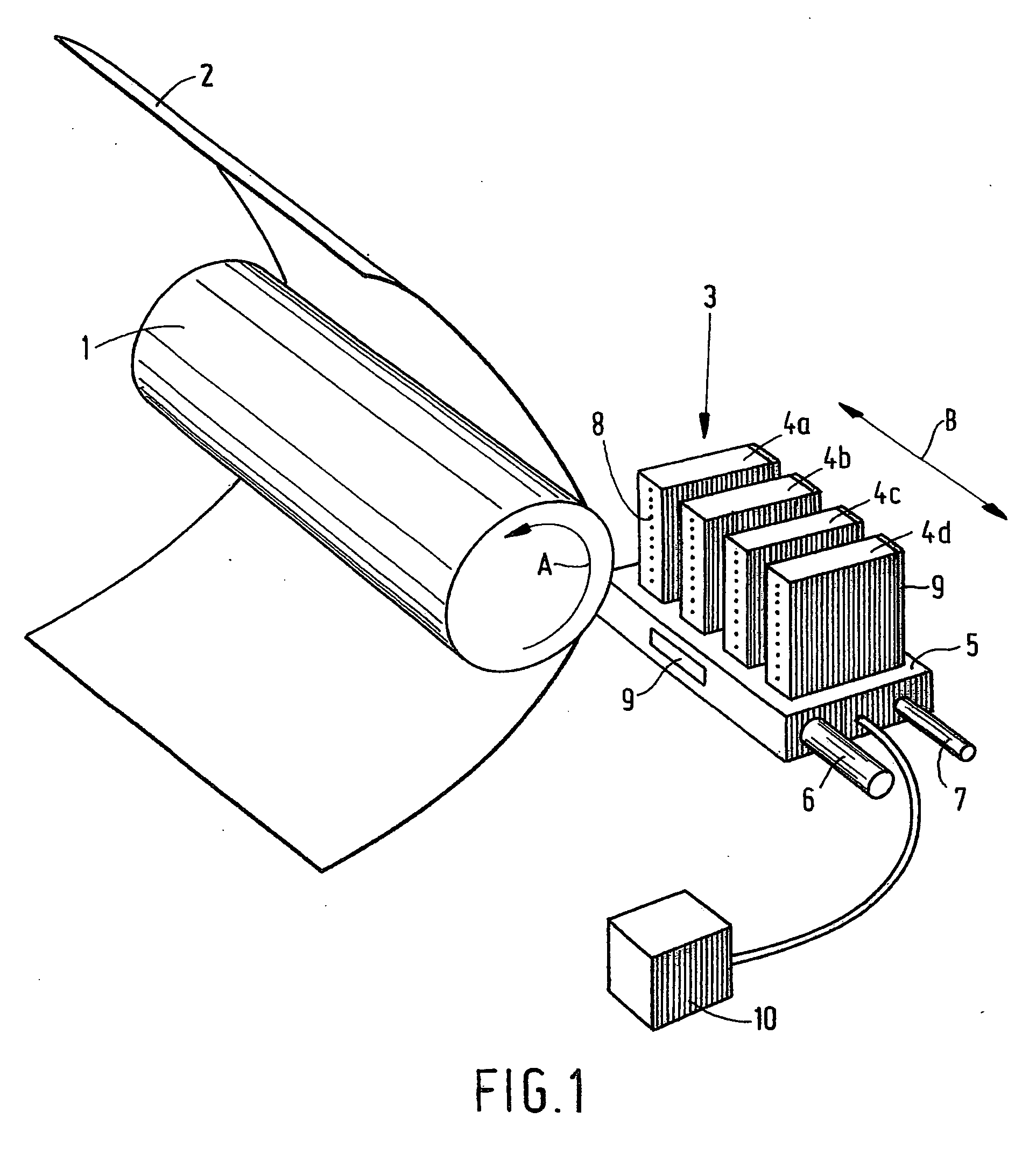
[0014]FIG. 1 is a diagram showing an inkjet printer. According to this embodiment, the printer comprises a roller 1 used to support a receiving medium 2, such as a sheet of paper or a transparency, and move it along the carriage 3. The carriage includes a carrier 5 to which four printheads 4a, 4b, 4c and 4d have been fitted. Each printhead contains its own color, in this case cyan (C), magenta (M), yellow (Y) and black (K) respectively. The printheads are heated using heating elements 9, which have been fitted to the rear of each printhead 4 and to the carrier 5. The temperature of the printheads is maintained at the correct level by the application of a central control unit 10 (controller).

[0015] The roller 1 may rotate around its own axis as indicated by arrow A. In this manner, the receiving medium may be moved in the sub-scanning direction (often referred to as the X direction) relative to the carrier 5, and therefore also relative to the printheads 4. The carriage 3 may be mov...


PUM


Abstract

A inkjet printhead containing two substantially closed ink chambers separated by a wall, each of the chambers having associated therewith an electromechanical converter, where actuation of the converter corresponding to a first chamber of said printhead will lead to a volume change in a second chamber due to cross-talk, whereby the wall is deformable in such a way that it deforms by actuation and as such simultaneously generates a second volume change in the same chamber, either volume change being, in essence, the same size but opposite to the other.

Description

[0001] This application claims priority to Dutch Application No. 1029190 filed on Jun. 6, 2005 in Dutch Patent Office, the entire contents of which is hereby incorporated by reference in its entirety. BACKGROUND OF THE INVENTION [0002] The invention relates to an inkjet printhead comprising two substantially closed ink chambers separated by a wall, each of the chambers comprising an electro-mechanical converter, where actuation of the converter corresponding to the first chamber of said printhead will lead to a volume change in the second chamber due to cross-talk. The invention also relates to an inkjet printer comprising this printhead. [0003] A printhead of this kind is known from U.S. Pat. No. 6,161,925. This printhead comprises a row of elongated ink chambers, also referred to as ink ducts, which by application of a machining technique have been fitted inside a so-called duct plate (element 12, see FIG. 1 of the corresponding patent). The chambers are covered by a compliant foi...

Claims


Application Information

Patent Timeline
Patent Type & Authority Applications(United States)
IPC IPC(8): B41J2/135
CPCB41J2/04525B41J2/04531B41J2/14274B41J2/04596B41J2/04581
Inventor WIJSHOFF, HERMANUS M.A.
Owner OCE TECH
Learn More