Electric drive unit, hybrid drive device, and vehicle

a hybrid drive and drive train technology, applied in the direction of vehicle sub-unit features, magnetic circuit shape/form/construction, magnetic circuit rotating parts, etc., can solve the problems of unsatisfactory performance of the described type of drive unit when using an asynchronous machine, too large installation space, and too heavy weight of the described drive unit, so as to reduce thermal load, increase output performance and efficiency, the effect of reducing production costs

Active Publication Date: 2019-12-10
VOLKSWAGEN AG
View PDF33 Cites 3 Cited by
  • Summary
  • Abstract
  • Description
  • Claims
  • Application Information

AI Technical Summary

Benefits of technology

[0005]The object of the invention is to further increase the output performance and the efficiency in the case of an electric drive unit for a hybrid drive system, in particular for a vehicle, of the described type and simultaneously to reduce the thermal load on the electric drive unit. The required installation space and also the production costs are simultaneously to be minimized.

Problems solved by technology

In light of increased demands on hybrid drives, the performance capability of a drive unit of the described type when using an asynchronous machine is described as unsatisfactory, the installation space is described as too large, the weight of said drive unit is described as too heavy and the power density is described as too low.
In contrast, the use of a more compact and more capable synchronous machine that is excited by permanent magnets leads to high costs owing to the expensive magnetic basic materials required, in particular neodymium, dysprosium and terbium.

Method used


Image

  • Electric drive unit, hybrid drive device, and vehicle
  • Electric drive unit, hybrid drive device, and vehicle
  • Electric drive unit, hybrid drive device, and vehicle

Examples


Embodiment Construction

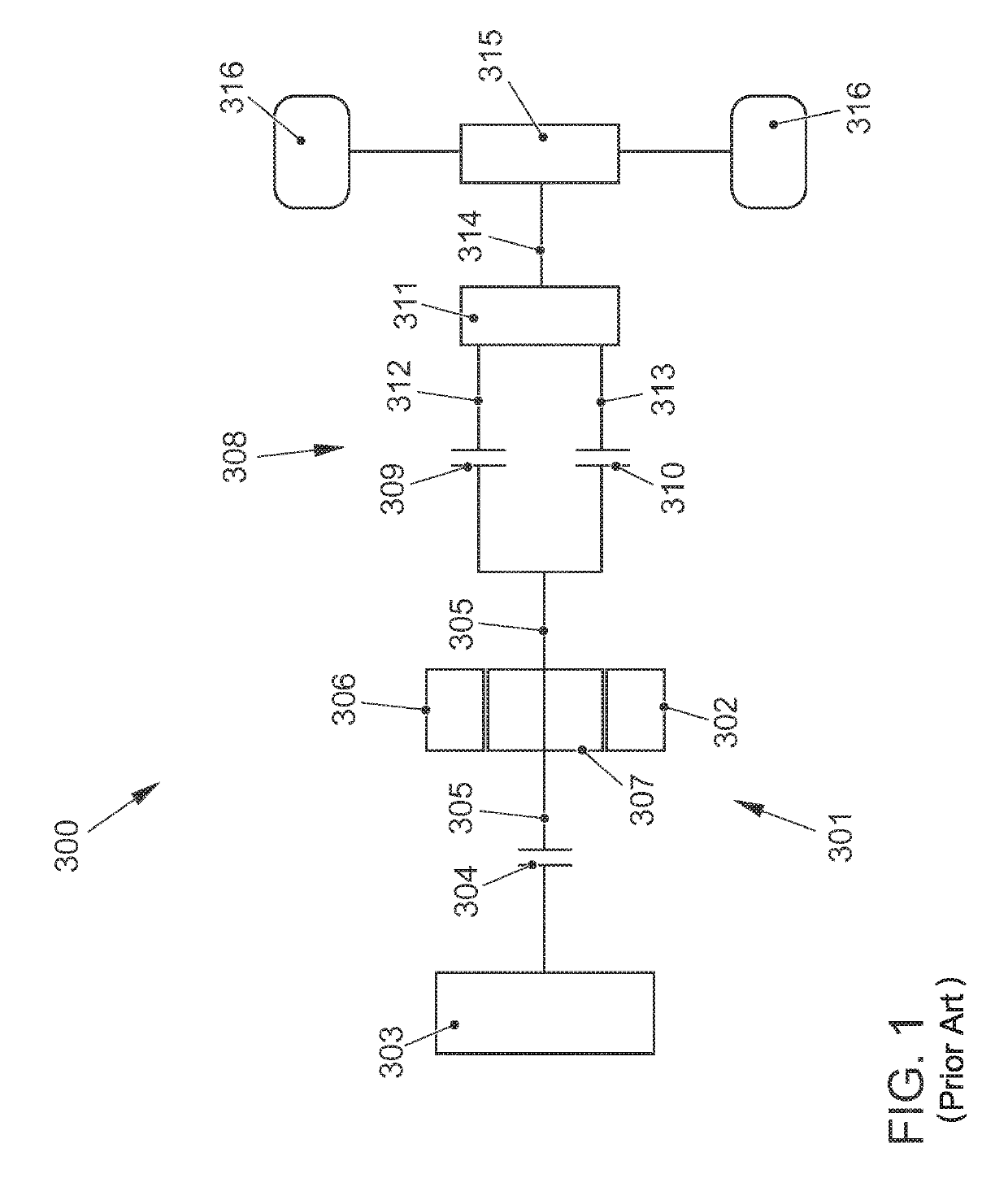
[0035]FIG. 1 illustrates a simplified schematic view of a drive train of a motor vehicle having a hybrid drive device 301 and said drive train is referred to with the reference numeral 300. The drive train 300 comprises the hybrid drive device 301 that is fitted with an electric drive unit 302, as is used in the prior art. Furthermore, the hybrid drive device 301 comprises an internal combustion engine 303 and a first clutch device 304 that is used to selectively connect and / or disconnect a force flow between the internal combustion engine 303 and an output element 305 of the electric drive unit 302. The electric drive unit 302 is configured with a stator 306 and a rotor 307. The rotor 307 is in particular configured with an arrangement of magnetic regions that is however not illustrated in detail in FIG. 1, said arrangement of magnetic regions having at least one permanent magnet and being connected in a non-positive locking manner to the output element 305. In particular, the outp...


PUM


Abstract

An electric drive unit for a hybrid drive, in particular for a vehicle, has an increased power output and degree of efficiency, while thermal loading as well as required installation space and manufacturing costs are minimized. The electric drive unit has an asynchronous machine with a rotor with a rotor cage, in particular a rotor cage which is formed with copper conductors. The asynchronous machine is formed with a stator having a shaft winding. The shaft winding is formed with a device for star-delta changeover. The rotor is formed with a rotor internal cooling device. A step-up gear mechanism is arranged in a power train between the rotor and the output element. There is also described a hybrid drive device with an electric drive unit, and a vehicle that has an electric drive unit and / or a hybrid drive device.

Description

[0001]The invention relates to an electric drive unit. The invention further relates to a hybrid drive device and a vehicle.PRIOR ART[0002]DE 103 49 558 A1 discloses a drive train for a hybrid drive system that comprises an internal combustion engine, an electric drive unit and a transmission unit. A first transmission clutch is arranged between an output shaft of the internal combustion engine and an input shaft of the transmission unit. The electric drive unit is arranged coaxially with respect to an axis of rotation of the input shaft. A plurality of known electric motors such as for example an asynchronous motor can be used as the electric drive unit. In the case of the described drive train, the constructive connection of the electric drive unit is to be simplified and the system efficiency is to be optimized. The first transmission clutch is configured as a switchable non-positive locking transmission clutch or a positive locking transmission clutch. The transmission clutch tr...

Claims


Application Information

Patent Timeline
Patent Type & Authority Patents(United States)
IPC IPC(8): B60K6/26H02K3/28H02K7/108B60L50/51B60L50/13B60K6/547B60K6/48H02P25/18H02K9/197B60K6/38B60K6/365H02K7/116H02K9/19H02K17/16H02K11/33B60K11/02B60K11/00H02K1/32B60K1/00
CPCH02P25/184B60L50/51B60K6/26B60K6/365H02K11/33B60K6/38B60K6/547H02K17/16H02K3/28H02K7/108H02K9/197B60L50/13H02K9/19B60K6/48H02K7/116H02K1/32B60K11/02Y02T10/6252Y02T10/6221Y02T10/641Y02T10/7005B60K2006/4825B60Y2306/03B60K2001/006B60K2006/4833B60K11/00Y02T10/70Y02T10/7077Y02T10/62Y02T10/64Y02T10/7072
Inventor THACKWELL, CLEEFSTOEHR, GERD
Owner VOLKSWAGEN AG
Why Eureka
Try Eureka