
Reducing variance in reach of WDM channels in an optical network

a wavelength division multiplex and optical network technology, applied in multiplex communication, electrical equipment, electromagnetic transmission, etc., can solve the problems of large amount of unused margin, poor network capacity, and limited reach of optical signals, even when using superchannels

Active Publication Date: 2019-12-17
FUJITSU LTD
View PDF26 Cites 10 Cited by
  • Summary
  • Abstract
  • Description
  • Claims
  • Application Information

AI Technical Summary

Benefits of technology

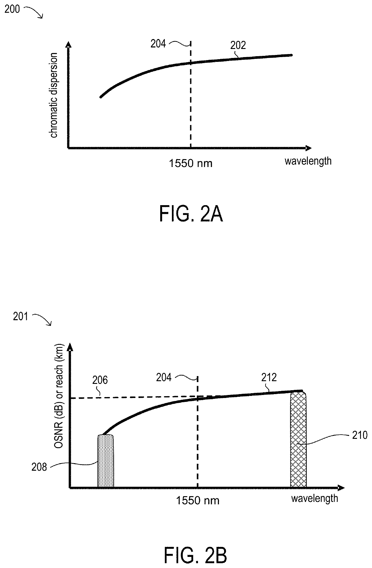
The patent describes a method for reducing the variance in the reach of wavelength division multiplexed (WDM) channels in optical transport networks. The method involves selecting an initial modulation format for each WDM channel based on its wavelength and calculating the expected reach of the channel. Reach extension techniques are then applied to the channels within a range of wavelengths to extend their reach to the target reach. The technique helps to ensure that channels within the lower portion of the range can achieve the target reach while refraining from applying the reach extension techniques to channels within the upper portion of the range. The method can be implemented using geometric shaping or probabilistic constellation shaping. The optical transport network includes a plurality of WDM channels, each assigned to a respective wavelength within a range of wavelengths. The network management system is responsible for selecting the initial modulation format for each channel and determining the target reach. The technique helps to improve the reliability and stability of the optical transport network.

Problems solved by technology

However, the reach of optical signals, even when using superchannels, may still be limited by optical signal-to-noise ratio (OSNR) levels experienced during transmission.
However, these networks may exhibit poor network capacity, with large amounts of unused margin for short reach optical transmission paths and in start-of-life scenarios.

Method used


Image

  • Reducing variance in reach of WDM channels in an optical network
  • Reducing variance in reach of WDM channels in an optical network
  • Reducing variance in reach of WDM channels in an optical network

Examples


Embodiment Construction

)

[0045]In the following description, details are set forth by way of example to facilitate discussion of the disclosed subject matter. It should be apparent to a person of ordinary skill in the field, however, that the disclosed embodiments are exemplary and not exhaustive of all possible embodiments.

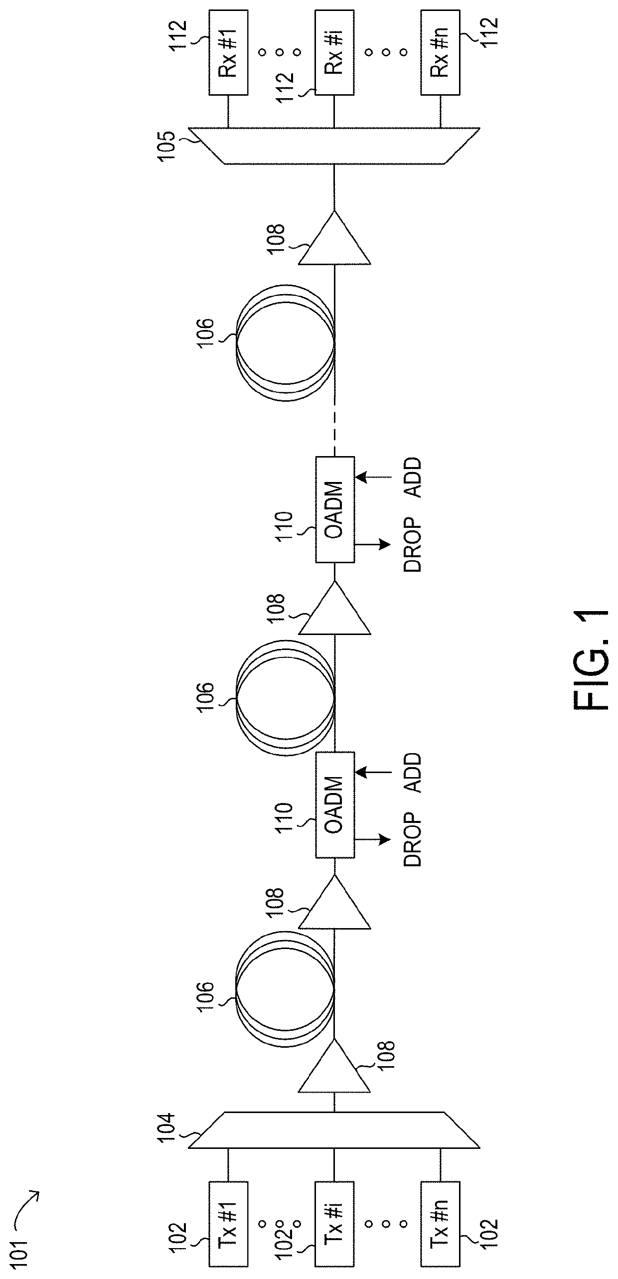
[0046]Referring now to the drawings, FIG. 1 illustrates an example embodiment of optical transport network (OTN) 101, which may represent an optical communication system. Optical transport network 101 included one or more optical fibers 106 to transport one or more optical signals communicated by components of optical transport network 101. The network elements of optical transport network 101, coupled together by fibers 106, may comprise one or more transmitters (Tx) 102, one or more multiplexers (MUX) 104, one or more optical amplifiers 108, one or more optical add / drop multiplexers (OADM) 110, one or more demultiplexers (DEMUX) 105, and one or more receivers (Rx) 112.

[0047]Optical tr...


PUM


Abstract

Systems and methods for reducing variance in reach of wavelength division multiplexed (WDM) channels in optical transport networks may include selecting, for each channel assigned to a respective wavelength, an initial modulation format and an initial distribution of constellation points in the complex plane, determining a target reach for all WDM channels that is achievable by higher wavelength channels but not by shorter wavelength channels, and applying one or more reach extension techniques to at least one shorter wavelength channel but not to the higher wavelength channels. The reach extension techniques may include probabilistic constellation shaping, symbol rate optimized subcarrier multiplexing, or a combination of the two. Transponders may be configurable to transmit or receive traffic over the WDM channels with or without implementing the reach extension techniques, as applicable.

Description

BACKGROUNDField of the Disclosure[0001]The present disclosure relates generally to optical communication networks and, more particularly, to reducing variance in reach of wavelength division multiplexed (WDM) channels in optical networks.Description of the Related Art[0002]Telecommunications systems, cable television systems and data communication networks use optical networks to rapidly convey large amounts of information between remote points. In an optical network, information is conveyed in the form of optical signals through optical fibers. Optical networks may also include various network nodes such as amplifiers, dispersion compensators, multiplexer / demultiplexer filters, wavelength selective switches, couplers, etc. to perform various operations within the network.[0003]Optical superchannels are an emerging solution for transmission of optical signals at 400 Gb / s and 1 Tb / s data rate per channel, and hold promise for even higher data rates in the future. A typical superchann...

Claims


Application Information

Patent Timeline
IPC IPC(8): H04B10/532H04B10/516H04B10/548H04B10/079H04B10/61
CPCH04B10/5161H04B10/548H04B10/07953H04B10/612H04B10/532H04B10/6162H04B10/516H04J14/0256
Inventor VASSILIEVA, OLGA I.KIM, INWOONGIKEUCHI, TADASHI
Owner FUJITSU LTD
Learn More