
Gas sensor

a technology of gas sensor and sensor, applied in the field of gas sensor, can solve the problems of not suggesting anything and the gas sensor cannot meet the needs, and achieve the effect of accurately measuring a concentration

Active Publication Date: 2019-12-24
NGK INSULATORS LTD
View PDF18 Cites 0 Cited by
  • Summary
  • Abstract
  • Description
  • Claims
  • Application Information

AI Technical Summary

Benefits of technology

[0018]According to the present invention, a gas sensor capable of measuring the concentration of an unburned hydrocarbon gas in a wide concentration range from low to high concentrations can be achieved.
[0019]The present invention therefore has an object to provide a gas sensor capable of accurately measuring a concentration of a target gas component in a concentration range larger than a conventional concentration range.

Problems solved by technology

Japanese Patent No. 5323752, however, discloses or suggests nothing about a mixed-potential gas sensor (needless to say, about its sensing electrode as well).
However, the measurement range of the concentration of a hydrocarbon gas by the gas sensor disclosed in Japanese Patent No. 4405643 is approximately 2000 ppmC at most, and such a gas sensor cannot meet the needs described above.

Method used


Image

  • Gas sensor
  • Gas sensor
  • Gas sensor

Examples


Embodiment Construction

First Configuration

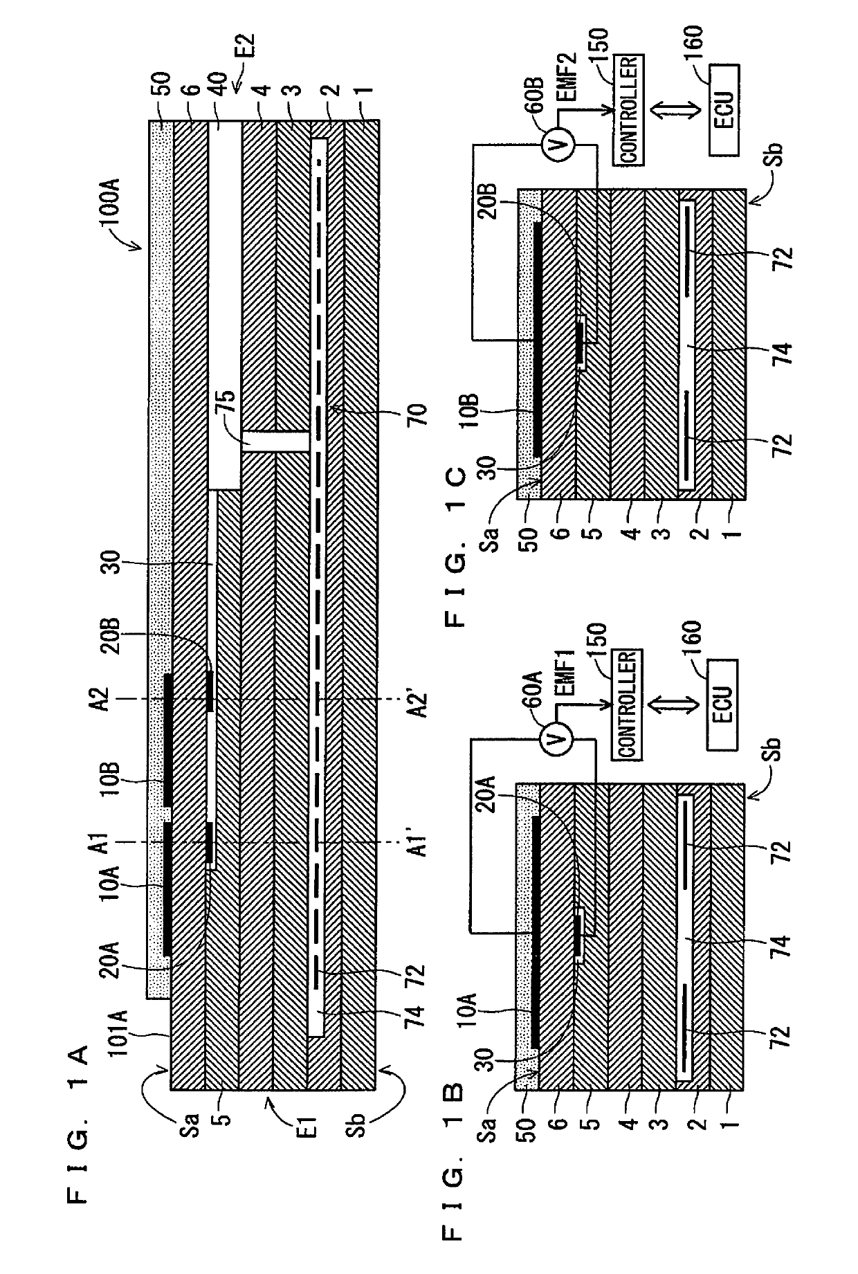
[0029]FIGS. 1A, 1B, and 1C are schematic sectional views schematically illustrating an example configuration of a gas sensor 100A according to a first configuration of the present invention. FIG. 1A is a vertical sectional view of a sensor element 101A that is a main component of the gas sensor 100A, which is taken along the longitudinal direction of the sensor element 101A. FIG. 1B is a view including a cross-section of the sensor element 101A perpendicular to the longitudinal direction of the sensor element 101A at a position A1-A1′ of FIG. 1A. FIG. 1C is a view including a cross-section of the sensor element 101A perpendicular to the longitudinal direction of the sensor element 101A at a position A2-A2′ of FIG. 1A.

[0030]The gas sensor 100A according to the first configuration of the present invention is a so-called mixed-potential gas sensor. Generally speaking, the gas sensor 100A determines the concentration of the gas component of a measurement gas using pot...


PUM

PropertyMeasurementUnit
thicknessaaaaaaaaaa
thicknessaaaaaaaaaa
porosityaaaaaaaaaa

Abstract

A mixed-potential gas sensor for measuring a concentration of a predetermined gas component of a measurement gas includes sensing electrodes mainly made of an oxygen-ion conductive solid electrolyte and located on a surface of a sensor element, and at least one reference electrode including a cermet including Pt and an oxygen-ion conductive solid electrolyte. The sensing electrodes each include a cermet including a noble metal and an oxygen-ion conductive solid electrolyte. The noble metal includes Pt and Au. A Au abundance ratio, which is an area ratio of a portion covered with the Au to a portion at which the Pt is exposed in a surface of noble metal particles forming each of the sensing electrodes, differs among the sensing electrodes. The gas sensor determines a concentration of the predetermined gas component based on a potential difference between each of the sensing electrodes and the at least one reference electrode.

Description

BACKGROUND OF THE INVENTION[0001]Field of the Invention[0002]The present invention relates to a gas sensor for sensing a predetermined gas component of a measurement gas, and more particularly, to a sensing electrode of the gas sensor.[0003]Description of the Background Art[0004]Gas sensors that sense a predetermined gas component of a measurement gas to determine its concentration come in various types such as a semiconductor gas sensor, a catalytic combustion gas sensor, an oxygen-concentration difference sensing gas sensor, a limiting current gas sensor, and a mixed-potential gas sensor (for example, see Japanese Patent Nos. 4405643, 4914447, and 5323752). Some of these gas sensors are obtained by providing electrodes containing a noble metal as its main constituent to a sensor element mainly made of ceramic that is a solid electrolyte such as zirconia.[0005]Japanese Patent No. 4405643 discloses a gas sensor provided with a thin layer mainly made of Pt or Au to compensate for the...

Claims


Application Information

Patent Timeline
Patent Type & Authority Patents(United States)
IPC IPC(8): G01N27/407G01N27/419
CPCG01N27/4076G01N27/419G01N27/4074G01N27/4073G01N27/4077G01N27/4071G01N27/4075
Inventor OKAMOTO, TAKUHIRATA, NORIKONAKAYAMA, YUKINAKASONE, OSAMU
Owner NGK INSULATORS LTD
Learn More