Method and apparatus for controlling an electric pump of a hydraulic braking circuit

a hydraulic braking circuit and electric pump technology, applied in the direction of electric variable regulation, process and machine control, instruments, etc., can solve the problems of increasing the power that can be drawn by the motor, increasing the cost of the motor, and not being desirable for a large motor. to achieve the effect of rapid pressure increas

Active Publication Date: 2020-01-21
TRW LIMITED
View PDF7 Cites 0 Cited by
  • Summary
  • Abstract
  • Description
  • Claims
  • Application Information

AI Technical Summary

Benefits of technology

[0012]In the past, the drive circuit has provided only a voltage limiting (buck) function, where the output voltage is always the same or less than the battery supply voltage. The invention here provides PWM control which enables the voltage applied to the motor to exceed the battery voltage. This provides the flexibility to decrease the time the motor needs to get up to speed by providing a period of increased power whilst managing the average current consumed over a given time by the motor. When operating in boost mode more power can be applied for a given average current, allowing a small motor to be used for a given pressure rise rate where a larger motor would be needed from a buck only controller. This reduces the need for larger and more expensive motors.
[0053]The method enables a rapid increase of pressure to be achieved whilst the average current drawn is maintained at a lower level than could be achieved using a prior art method that does not provide for a voltage boost.

Problems solved by technology

However, larger motors are not desirable as they are more costly than smaller motors.
The power that can be drawn by the motor is limited in prior art systems by the voltage available from the battery.
Using a more powerful motor will draw more current but this is often not desirable.
Drawing more current not only increases the power consumption but increases the rate at which the battery will drain.
Too much current can cause the battery to run flat.
Another possible problem that can occur with high current drain is that it can cause the wiring loom to overheat.
This could be ameliorated by increasing the gauge of the wires in the loom, but this increases cost and weight.

Method used


Image

  • Method and apparatus for controlling an electric pump of a hydraulic braking circuit
  • Method and apparatus for controlling an electric pump of a hydraulic braking circuit
  • Method and apparatus for controlling an electric pump of a hydraulic braking circuit

Examples


Embodiment Construction

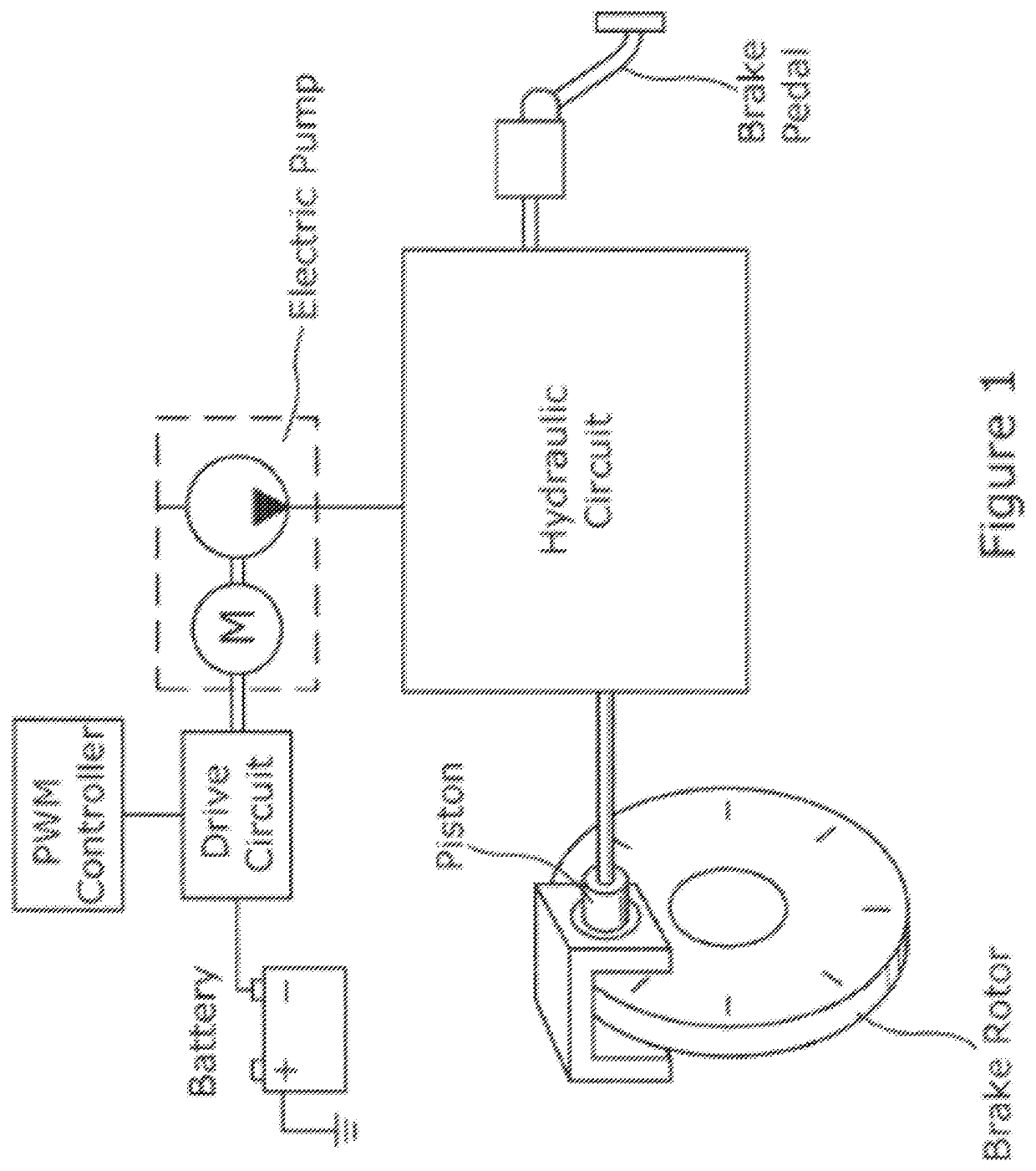
[0060]As shown in FIG. 1, a vehicle (not shown) includes a hydraulic braking circuit that supplied hydraulic fluid to a piston of one brake. The piston presses a pad against a rotor, the pressure applied being determined by the pressure of the fluid. In normal running the pad is held clear of the rotor and the rotor turns freely with the associated wheel of the vehicle. During braking the pressure is increased, which causes the friction force between the pad and rotor to increase. This generates heat, and the conversion of the rotational energy of the disk to heat is the main mechanism by which the brakes slow the wheel of the vehicle.

[0061]The pressure of the fluid is controlled by a driver pressing a brake pedal, which operates a master cylinder. In addition, a pump is provided in the circuit. The pump includes an electric motor and at least one piston, the piston moves as power is supplied to the motor, and this movement of the piston pressurises the fluid in the circuit. The pum...


PUM


Abstract

A drive circuit for an electric motor of the type which forms part of a pump in a hydraulic braking circuit of a vehicle comprises an input node, an output node and a voltage and current regulating circuit which connects the nodes and which varies the voltage and current supplied to the output node from the input node in response to a modulation strategy, the input node in use being connected to a battery supply of a vehicle and the output node connected to one side of the electric motor. The voltage and current regulating circuit comprises a switch mode power supply circuit capable of providing at the output node a voltage that is either above or below the battery supply voltage at the input node.

Description

CROSS-REFERENCE TO RELATED APPLICATIONS[0001]This application is the National Phase of International Application PCT / GB2015 / 053753 filed Dec. 8, 2015 which designated the U.S. and that International Application was published in English under PCT Article 21(2) on Jun. 16, 2016 as International Publication Number WO 2016 / 092289 A1. PCT / GB2015 / 053753 claims priority to Great Britain Application No. 1421791.3, filed Dec. 8, 2014. Thus, the subject nonprovisional application claims priority to Great Britain Application No. 1421791.3, filed Dec. 8, 2014. The disclosures of both applications are incorporated herein by reference.BACKGROUND OF THE INVENTION[0002]This invention relates to improvements in controller circuits for an electric pump incorporated into braking circuits for vehicles and to an improved method of operating an electric pump.[0003]It is known to provide a hydraulic braking circuit of a vehicle of the kind comprising a hydraulic circuit connecting a source of pressure to ...

Claims


Application Information

Patent Timeline
Patent Type & Authority Patents(United States)
IPC IPC(8): H02M3/158B60T17/02B60T7/04G05F1/575B60R16/033
CPCB60T7/042B60T17/02H02M3/1582G05F1/575B60R16/033
Inventor VINCENT, KENNETH
Owner TRW LIMITED
Why Eureka
Try Eureka