
Work machine provided with parallel link mechanism

a technology of parallel link mechanism and work machine, which is applied in mechanical devices, manufacturing tools, and gearing, etc., can solve the problems of increasing the size of the apparatus, the rigidity of the entire mechanism is low, and the entire mechanism is large in dimensions, so as to reduce the cost, reduce the stroke of the linear motion mechanism, and compact the effect of configuration

Active Publication Date: 2020-02-11
NTN CORP
View PDF27 Cites 3 Cited by
  • Summary
  • Abstract
  • Description
  • Claims
  • Application Information

AI Technical Summary

Benefits of technology

[0009]Regarding the parallel link mechanism of Patent Document 1, the configuration thereof is comparatively simple, and the operating angle of each link is small. Thus, there is a problem in that if the operating range of a travelling plate is set to be large, the link length is increased, thus resulting in large dimensions of the entire mechanism, which leads to an increase in the size of the apparatus. There is also a problem in that the rigidity of the entire mechanism is low, and thus the weight of a tool to be mounted on the travelling plate, that is, the weight capacity of the travelling plate, is limited to a small value.

Problems solved by technology

Thus, there is a problem in that if the operating range of a travelling plate is set to be large, the link length is increased, thus resulting in large dimensions of the entire mechanism, which leads to an increase in the size of the apparatus.
There is also a problem in that the rigidity of the entire mechanism is low, and thus the weight of a tool to be mounted on the travelling plate, that is, the weight capacity of the travelling plate, is limited to a small value.
However, the link actuation device of Patent Document 2 or 3 has a problem in that when the link actuation device is used in combination with another mechanism, the size of the entire apparatus is increased.

Method used


Image

  • Work machine provided with parallel link mechanism
  • Work machine provided with parallel link mechanism
  • Work machine provided with parallel link mechanism

Examples


Embodiment Construction

[0053]A work apparatus provided with a parallel link mechanism according to an embodiment of the present invention will be described with reference to FIGS. 1 to 9.

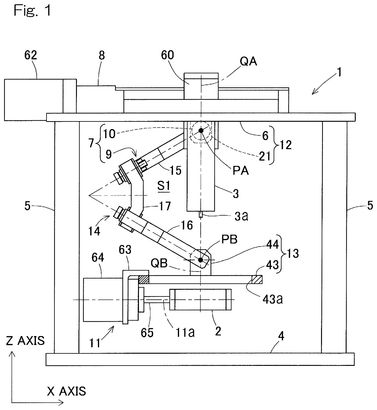
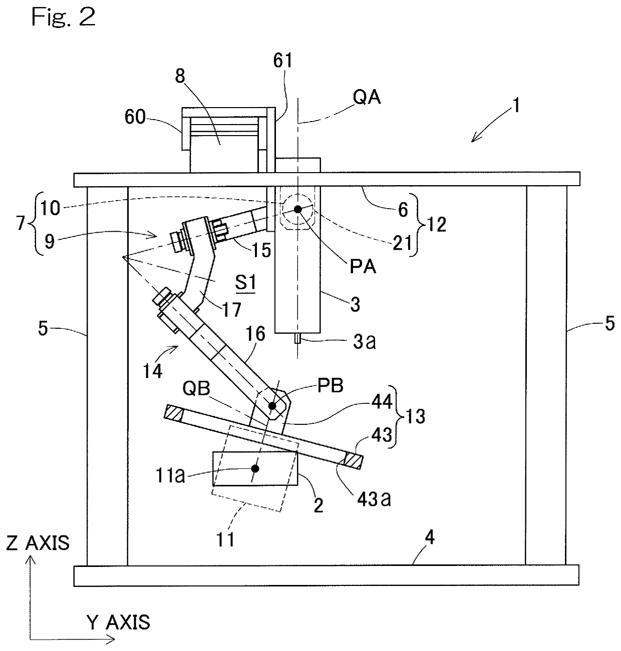
[0054]FIG. 1 is a front view of a work apparatus 1 of the present embodiment, and FIG. 2 is a side view of the work apparatus 1. The work apparatus 1 is an apparatus that performs non-contact operation on a work object 2 with a working body 3. A horizontal proximal end member 6 is supported by a plurality of posts 5 that are provided on a base plate 4 so as to project therefrom. A link actuation device 7 and an X-axis linear motion mechanism 8 are mounted on the proximal end member 6. To be exact, the proximal end member 6 forms a part of the link actuation device 7.

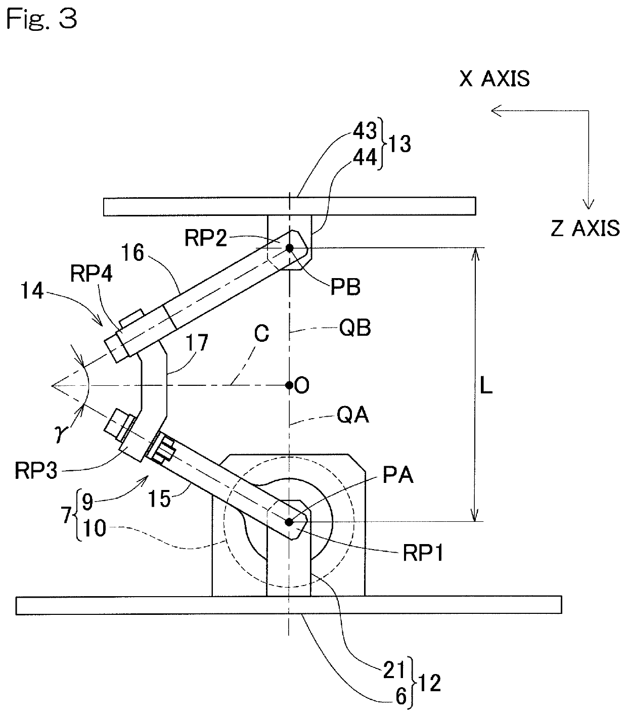
[0055]The link actuation device 7 includes: a parallel link mechanism 9 that supports a rotating mechanism 11 and a work object 2 in a position-changeable fashion; and position control actuators 10 that operate the parallel link mechanism 9. The X-axis linear ...


PUM


Abstract

A work apparatus includes a parallel link mechanism, a position control actuator, a linear motion mechanism, and a rotating mechanism. The parallel link mechanism includes three or more link mechanisms that couple a distal end side link hub to a proximal end side link hub such that a position of the distal end side link hub can be changed relative to the proximal end side link hub. The position control actuator operates the parallel link mechanism. The linear motion mechanism moves a working body in an axial direction orthogonal to a central axis of the proximal end side link hub. The rotating mechanism is mounted on the distal end side link hub and rotates a work object about a rotation center axis parallel to a movement direction of the linear motion mechanism when the central axis and a central axis are on the same line.

Description

CROSS REFERENCE TO THE RELATED APPLICATIONS[0001]This application is a U.S. national stage application, which claims the benefit under 35 USC § 371 of PCT International Patent Application No. PCT / JP2016 / 073375, filed Aug. 9, 2016, which claims foreign priority benefit under 35 USC § 119 of Japanese patent application No. 2015-158208, filed Aug. 10, 2015, the entire disclosures of which is herein incorporated by reference.BACKGROUND OF THE INVENTION[0002](Field of the Invention)[0003]The present invention relates to a work apparatus including a parallel link mechanism to be used in equipment, such as medical equipment and industrial equipment, which requires high-speed, high-accuracy, and wide operating range.[0004](Description of Related Art)[0005]Parallel link mechanisms and link actuation devices to be used in various types of work apparatuses such as medical equipment and industrial equipment are proposed in Patent Documents 1, 2, and 3.RELATED DOCUMENTPatent Document[0006][Paten...

Claims


Application Information

Patent Timeline
Patent Type & Authority Patents(United States)
IPC IPC(8): B23Q1/44B25J11/00F16H21/48F16H25/22F16H21/54
CPCB25J11/00F16H21/48B23Q1/44F16H21/54F16H25/2204B23Q1/25B23Q1/5456B25J9/0048B25J9/0072B25J9/0096
Inventor NOSE, KENZOUISOBE, HIROSHISAKATA, SEIGOYAMADA, HIROYUKI
Owner NTN CORP
Learn More