

Enhanced remote surveying systems and methods
a remote surveying and remote technology, applied in the field of position measurement and surveying, can solve the problems of difficult deployment of high-precision gnss in applications that may involve significant gnss signal blocking and/or signal degradation, adverse effects on the use of such high-precision gnss receivers, and affecting the accuracy of such receivers
- Summary
- Abstract
- Description
- Claims
- Application Information
AI Technical Summary
Benefits of technology
Problems solved by technology
Method used
Image

Examples
Embodiment Construction
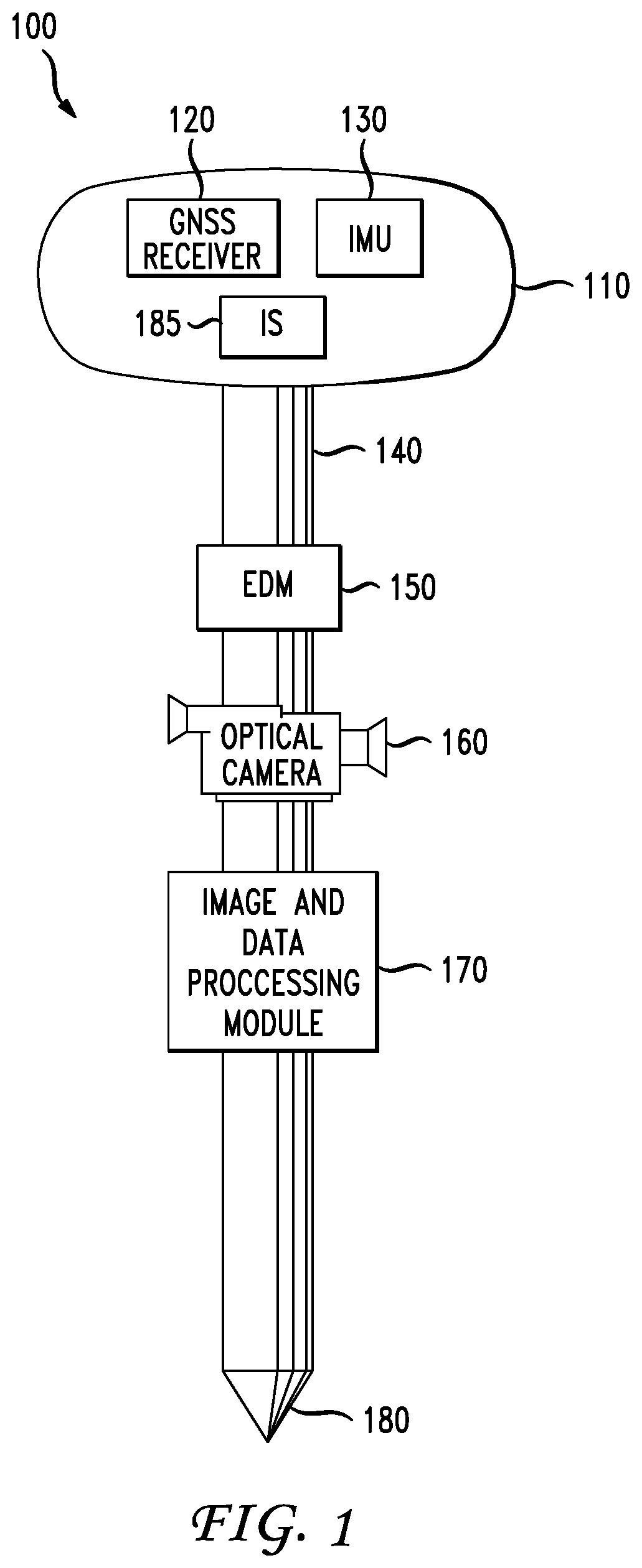
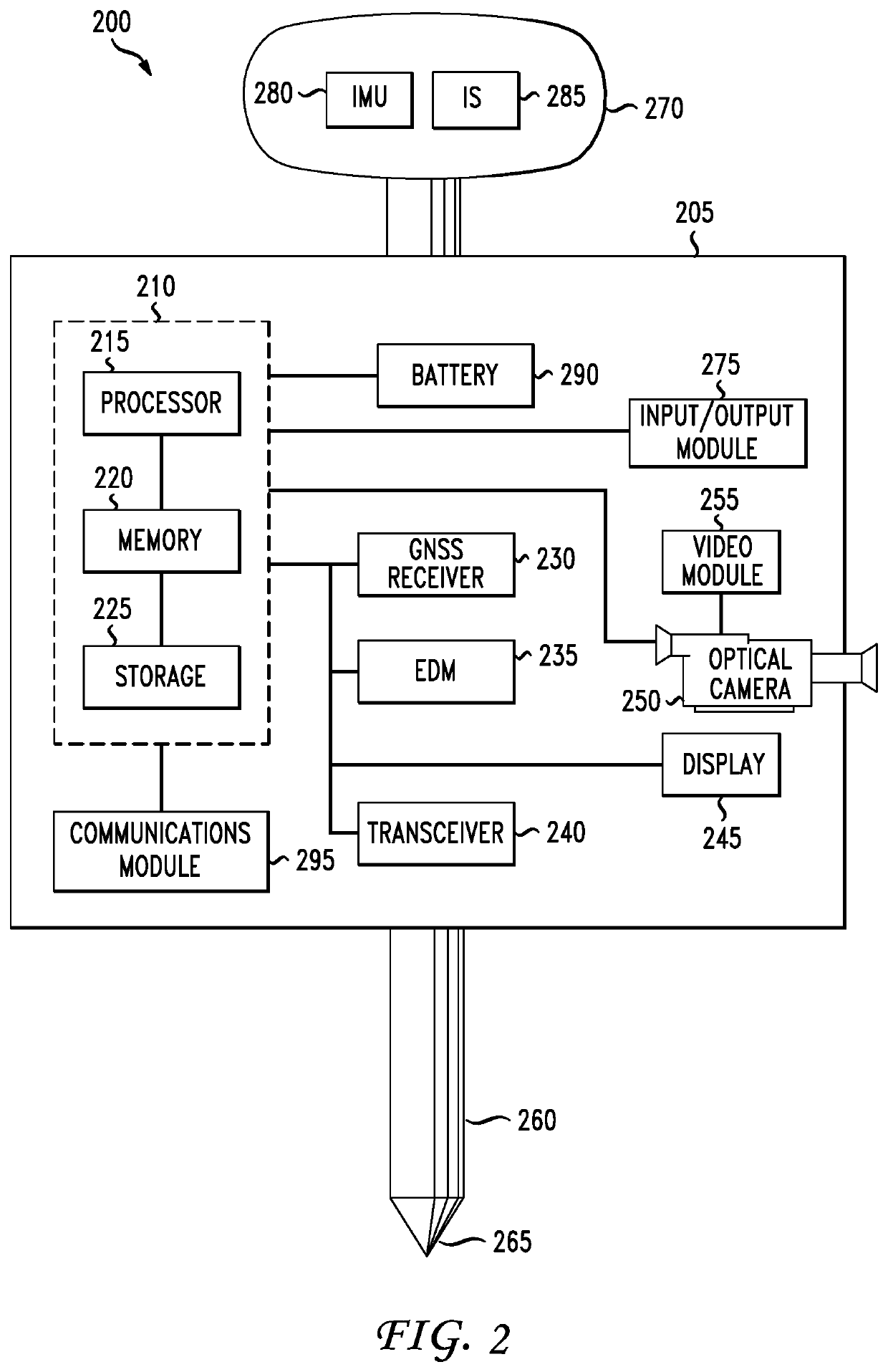
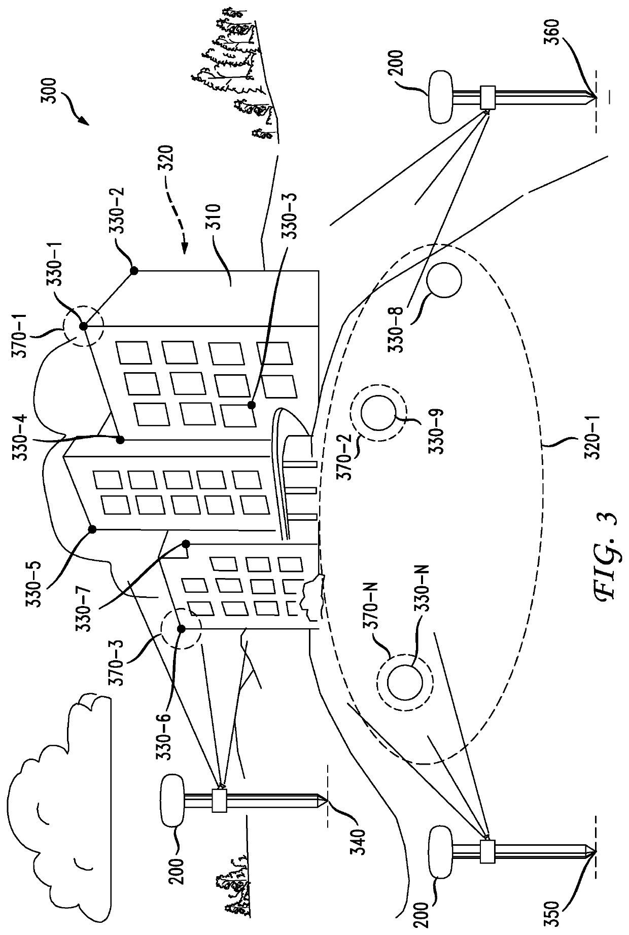
[0007]In accordance with various embodiments, a method and apparatus is provided that utilizes a high-precision GNSS receiver, an EDM and an optical camera in combination for making accurate measurements of multiple remote target points associated with a selected target.
[0008]More particularly, in accordance with an embodiment, the accurate measurement of a plurality of remote points is facilitated by integrating a high-precision GNSS receiver, an EDM and an optical camera such that their combined physical location and orientation can be measured and known, and allowing for a single calibration thereof. This integration may take various forms such as a single, integrated device, or individual devices assembled together on a surveying pole, for example. In accordance with a further embodiment, the integrated device may also include one or more sensors such as an inclination sensor (i.e., inclinometer) and an inertial measurement unit (IMU) for further capturing orientation measuremen...
PUM
 Abstract
Description
Claims
Application Information