Device and method for controlling group velocity delays of pulses propagating in monomode optical fibers of a fiber bundle

a monomode optical fiber and group velocity delay technology, applied in the direction of cladded optical fibre, instruments, optical elements, etc., can solve the problems of difficult control of the imaging plane along the optical axis, inability to design a miniature microscope comprising a light source, a focusing lens, and a camera at the distal end (that is, located at the end of the fiber, side with the specimen) of a medical endoscope,

Active Publication Date: 2020-02-25
CENT NAT DE LA RECHERCHE SCI +1
View PDF10 Cites 2 Cited by
  • Summary
  • Abstract
  • Description
  • Claims
  • Application Information

AI Technical Summary

Benefits of technology

Thus, the device for transporting and controlling according to the present specification is able to minimize the standard deviation for the set of values formed by the group delays of the pulses in the fibers, regardless of the bundle of fibers used and even if the bundle of fibers is displaced or deformed; this is made possible by the simple programming of each of the spatial light modulators so as to form elementary beams each elementary beam intended to pass into each of the fibers of the bundle of fibers and to control their displacement so that they pass into the appropriate waveplate.
The device for transporting and controlling according to the present specification may also make possible, by programming of one and / or the other of the spatial light modulators, the application of a phase shift to each of the elementary beams, enabling the imprinting at the distal end of the bundle of fibers of a predetermined phase function and / or the correcting of the phase variations introduced by each of the fibers of the bundle of fibers.
The device for transporting and controlling according to the present specification may also make possible the transporting and controlling of beams formed of pulses with different wavelengths, by programming of the first spatial light modulator in order to assure the distribution of the elementary light beams formed of pulses at different wavelengths in the subset of distinct fibers of the bundle of fibers.
According to one or more sample embodiments, the one and / or the other of the spatial light modulators makes possible the application of a phase shift to each of the elementary beams, making it possible to imprint at the distal end of the bundle of fibers a predetermined phase function and / or to correct the phase variations introduced by each of the fibers of the bundle of fibers.

Problems solved by technology

On the one hand, the design of a miniature microscope comprising a light source, a focusing lens, and a camera at the distal end (that is, located at the end of the fiber, at the side with the specimen) of a medical endoscope is not feasible due to the bulky size of the components involved.
On the other hand, the increasing interest in nonlinear imaging for endo-microscopy requires one to work with light pulses having strong light intensity, which is not always compatible with fiber systems.
However, the presence of a piezoelectric scanner at the tip of the fiber limits the diameter below which the distal portion of the endoscope can be miniaturized (typically on the order of 3 mm); furthermore, control of the imaging plane along the optical axis is hard to carry out.
Finally, this approach is limited to nonlinear imaging which requires the use of ultrashort pulses (typically less than a picosecond).
In fact, standard optical fibers have a strong dispersion which is hard to pre-compensate and they are subject to nonlinear effects which affect the spectral and temporal profiles of the light pulse delivered at the tip of the fiber.
However, as in the previously described approach, the entire light circulates in the core of a single optical fiber and the maximum peak power is limited due to intrinsic nonlinear effects present in the optical fibers of the bundle of fibers.
It is therefore difficult to perform a nonlinear imaging which requires ultrashort pulses, and thus elevated peak powers.
However, the transmission matrix of the fiber is complex and highly dependent on the curvature of the MMF optical fiber.
Furthermore, due to the multimode nature, a short pulse at the proximal portion is greatly elongated at the distal portion, which limits the possible applications to nonlinear imaging.
However, the patent applicants have shown that, in a nonlinear imaging mode, i.e., when ultrashort pulses are sent along the bundle of monomode optical fibers, typically being pulses with duration less than a picosecond, the group delays of the pulses traveling in the different optical fibers may generate a loss of light intensity at the specimen.
These group delays are introduced by each of the monomode optical fibers Fi and result in intrinsic inhomogeneities appearing inevitably during the fabrication of the fiber as well as inhomogeneities induced by constraints during a deformation and / or during a movement of the fiber.

Method used


Image

  • Device and method for controlling group velocity delays of pulses propagating in monomode optical fibers of a fiber bundle
  • Device and method for controlling group velocity delays of pulses propagating in monomode optical fibers of a fiber bundle
  • Device and method for controlling group velocity delays of pulses propagating in monomode optical fibers of a fiber bundle

Examples


Embodiment Construction

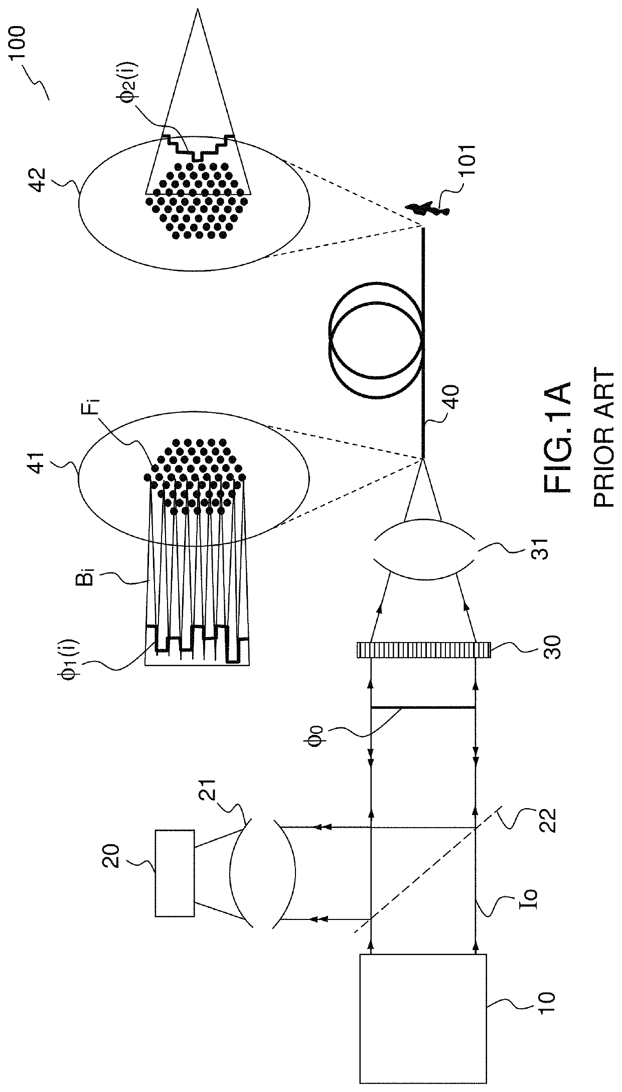
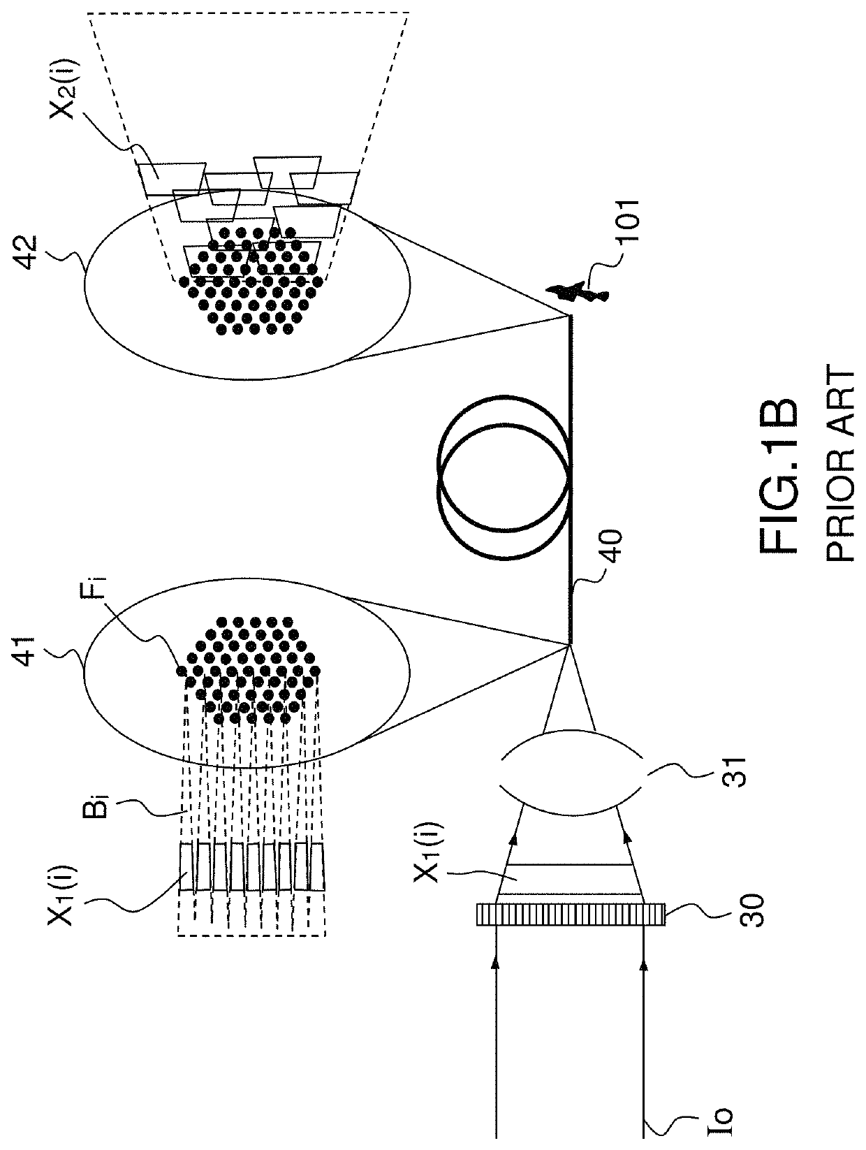
In the figures, the identical elements are indicated by the same references.

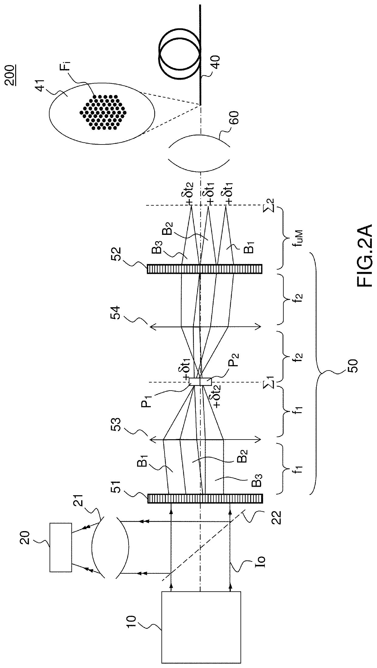
FIGS. 2A and 2B illustrate schematically a system 200 of “lensless” endo-microscopic imaging according to the present description as well as the principle of its implementation.

The system 200 generally comprises an emission path, with a light source 10 for the emitting of ultrashort light pulses I0, typically less than a picosecond, for example between 100 femtoseconds and a picosecond, and a detection path adapted to detect the light intended to pass through the bundle of monomode optical fibers 40 from its distal end to its proximal end. The light detected is, for example, the light coming from the nonlinear process in the specimen after excitation. The detection path comprises a lens 21 and a detector 20 and it is separated from the emission path by a separating plate 22, such as a dichroic plate in the case of nonlinear imaging applications in which the detection wavelength (for example, two-photon fluor...


PUM

PropertyMeasurementUnit
diameteraaaaaaaaaa
diameteraaaaaaaaaa
diameteraaaaaaaaaa

Abstract

According to one aspect, the invention concerns a device for transporting and controlling light pulses for lensless endo-microscopic imaging and comprises:a bundle of N monomode optical fibers (Fi) arranged in a given pattern, each monomode optical fiber being characterized by a relative group delay value (Ax) defined relative to the travel time of a pulse propagating in a reference monomode optical fiber (F0) of the bundle of fibers (40),an optical device for controlling group velocity (50) comprising a given number M of waveplates (Pj) characterized by a given delay (8tj); a first spatial light modulator (51) suitable for forming from an incident light beam a number N of elementary light beams (Bi) each of which is intended to enter into one of said optical fibers, each elementary beam being intended to pass into a given waveplate such that the sum of the delay introduced by said waveplate and the relative group delay of the optical fiber intended to receive said elementary light beam is minimal in absolute value; a second spatial light modulator (52) suitable for deviating each of the N elementary light beams such that each elementary light beam penetrates into the corresponding optical fiber perpendicularly to the entrance face of the optical fiber.

Description

PRIOR ARTTechnical Field of the InventionThe present invention concerns a device for transporting and controlling light pulses for so-called “lensless” endo-microscopic imaging, as well as systems and methods of lensless endo-microscopic imaging, in particular nonlinear imaging. It applies in particular to the endoscopic exploration of organs in a living creature, human or animal.Prior ArtDevelopments in endo-microscopic imaging require the use of optomechanical fiber devices having specific features as compared to the imager systems in free space.On the one hand, the design of a miniature microscope comprising a light source, a focusing lens, and a camera at the distal end (that is, located at the end of the fiber, at the side with the specimen) of a medical endoscope is not feasible due to the bulky size of the components involved. One therefore looks for solutions enabling an imaging at the tip of an optical fiber while limiting the size of the endoscope at the distal end.On the ...

Claims


Application Information

Patent Timeline
Patent Type & Authority Patents(United States)
IPC IPC(8): G02B6/02G02B23/24G02B21/00G02B6/06G02B23/26H01S3/00
CPCG02B23/26H01S3/0057G02B23/2469G02B21/0004G02B6/06G02B6/065G02B6/02042
Inventor ANDRESEN, ESBENRIGNEAULT, HERVÉ
Owner CENT NAT DE LA RECHERCHE SCI
Why Eureka
Try Eureka