High-pressure tank and method of manufacturing the same

a high-pressure tank and high-pressure technology, which is applied in the field of high-pressure tanks, can solve the problems that the study of tank performance improvement has not been made, and achieve the effects of reducing the shear stress generated between the large-angle layer and reducing the risk of fiber winding collapse in the helical layer group, and reducing the risk of fiber winding collaps

Active Publication Date: 2020-08-06
TOYOTA JIDOSHA KK
View PDF3 Cites 2 Cited by
  • Summary
  • Abstract
  • Description
  • Claims
  • Application Information

AI Technical Summary

Benefits of technology

[0006](1) An aspect of the disclosure relates to a high-pressure tank. The high-pressure tank includes: a liner having an internal space in which to store a fluid; and a reinforcing layer including a fiber wound around the liner and a resin, and provided on an outer surface of the liner such that the outer surface of the liner is covered with the reinforcing layer. The reinforcing layer includes: a helical layer group including laminated helical layers in each of which the fiber is helically wound; and a large-angle layer provided at a position that is adjacent to the helical layer group and that is on a side close to the liner. The large-angle layer is larger in fiber winding angle than any of the helical layers of the helical layer group. The fiber winding angle is a winding angle of the fiber with respect to a direction of an axis of the high-pressure tank. The helical layer group includes an innermost layer, an outermost layer, and an intermediate layer. The innermost layer is disposed closest to the liner. The innermost layer is one of a first helical layer having a largest fiber winding angle among the helical layers of the helical layer group and a second helical layer having a second largest fiber winding angle among the helical layers of the helical layer group. The outermost layer is disposed closest to an outer surface of the high-pressure tank. The outermost layer is the other one of the first helical layer and the second helical layer. The intermediate layer is disposed between the innermost layer and the outermost layer. The intermediate layer includes a helical layer having a fiber winding angle that is smaller than each of a fiber winding angle of the innermost layer and a fiber winding angle of the outermost layer. With the configuration of the high-pressure tank according to this aspect, the difference in fiber winding angle between the large-angle layer and the helical layer group can be made smaller. Thus, a shear stress generated between the large-angle layer and the helical layer group can be kept low, whereby the durability of the high-pressure tank can be improved. Further, it is easy to appropriately set a difference in fiber winding angle between adjacent layers in the helical layer group. Consequently, the occurrence of fiber winding collapse in the helical layer group can be restrained. Thus, it is possible to easily curb reduction in the strength and durability of the high-pressure tank due to fiber winding collapse. As a result, the performance of the high-pressure tank can be improved. (2) In the high-pressure tank according to the above aspect, fiber winding angles of the helical layers disposed adjacent to each other in the helical layer group may be different from each other. With this configuration of the high-pressure tank, the occurrence of fiber winding collapse in the helical layer group can be restrained. Thus, it is possible to enhance the effect of curbing reduction in the strength and durability of the high-pressure tank due to fiber winding collapse. (3) In the high-pressure tank according to the above aspect, the innermost layer may be the first helical layer, and the outermost layer may be the second helical layer. With this configuration of the high-pressure tank, it is possible to reduce a stress generated in the reinforcing layer. Thus, it is possible to enhance the effect of improving the durability of the high-pressure tank. (4) In the high-pressure tank according to the above aspect, the helical layers of the helical layer group may be laminated in such an order that a standard deviation in a case where a group of differences in fiber winding angle between the helical layers adjacent to each other is used as a population is minimized. With this configuration of the high-pressure tank, the physical properties of the layers of the helical layer group are made more uniform by reducing the variations in the difference in fiber winding angle between adjacent helical layers in the helical layer group, and thus generation of a stress in the helical layer group can be reduced. The disclosure may be implemented in various aspects other than the above aspect. For example, the disclosure may be implemented in an aspect related to a method of manufacturing a high-pressure tank.

Problems solved by technology

However, sufficient studies have not been made on the improvement of tank performance, such as durability of the entire tank, in consideration of the positional relationship between these layers in the reinforcing layer.

Method used


Image

  • High-pressure tank and method of manufacturing the same
  • High-pressure tank and method of manufacturing the same
  • High-pressure tank and method of manufacturing the same

Examples


first embodiment

A. First Embodiment

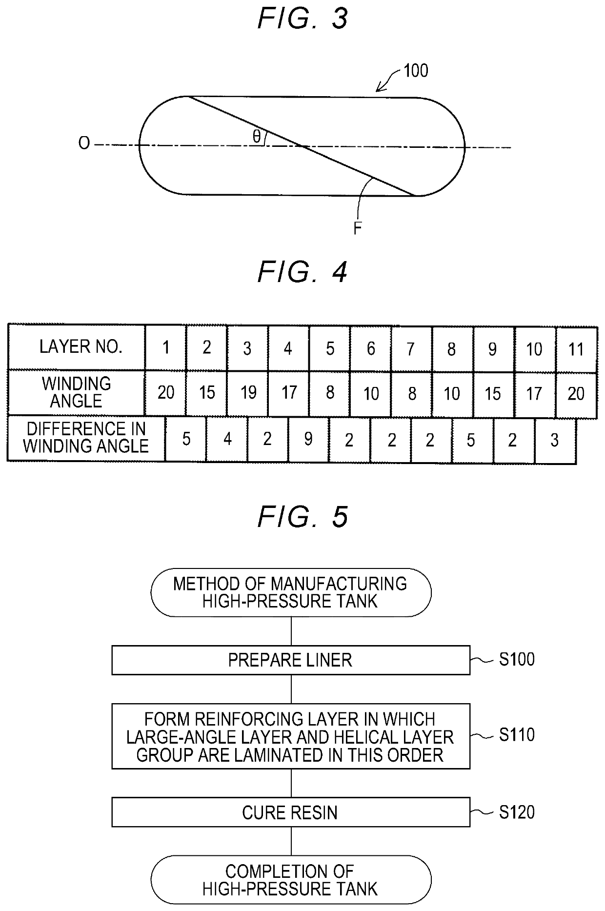
[0016]A-1. Overall Configuration of High-Pressure Tank

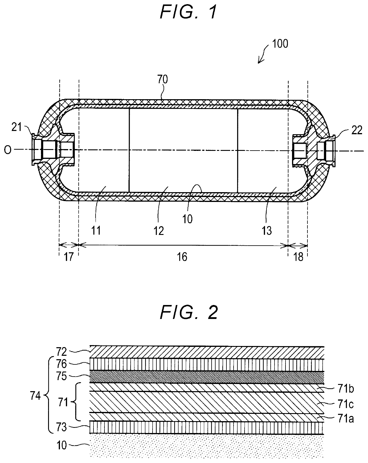
[0017]FIG. 1 is a schematic sectional view of a high-pressure tank 100 according to a first embodiment of the present disclosure. The high-pressure tank 100 is configured to store a high-pressure fluid. In the present embodiment, the high-pressure tank 100 stores compressed hydrogen as a fluid, and is mounted in, for example, a fuel cell vehicle that is a hydrogen tank-equipped vehicle. The high-pressure tank 100 includes a liner 10, a reinforcing layer 70, and caps 21, 22. Note that FIG. 1 and other drawings (described later) schematically illustrate various portions of the high-pressure tank 100 according to the present disclosure, and therefore the sizes of the various portions illustrated in the drawings do not represent specific sizes.

[0018]A space in which to store a high-pressure gas is defined in the liner 10. The liner 10 includes a cylindrical portion 16 having a cylindrical shape and extending in a d...

second embodiment

B. Second Embodiment

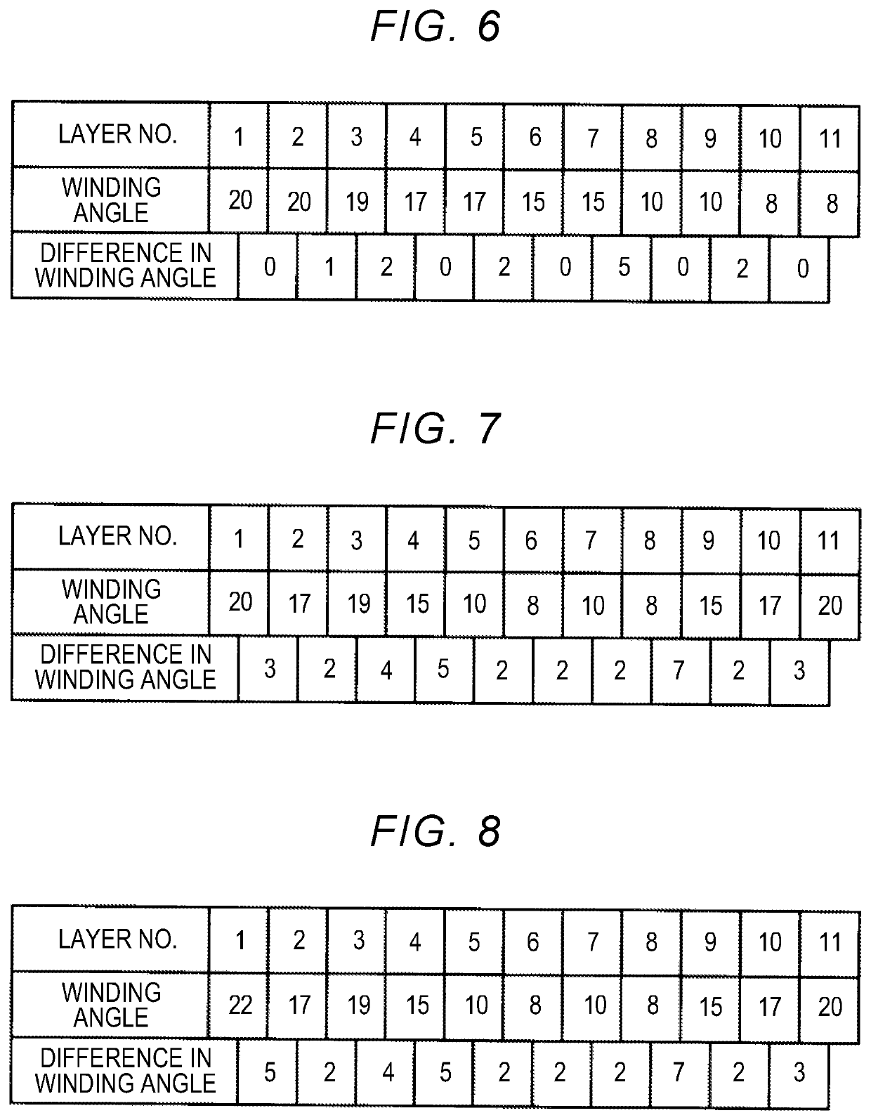
[0045]FIG. 7 is a diagram illustrating, in a manner similar to that in FIG. 4, an example of the configuration of the helical layer group 71 of the high-pressure tank 100 according to a second embodiment. The high-pressure tank 100 of the second embodiment has the same structure as that of the high-pressure tank 100 of the first embodiment, except for the configuration of the helical layer group 71. FIG. 7 illustrates an example in which eleven small-angle helical layers are provided as in the helical layer group 71 illustrated in FIG. 4. In the second embodiment, the helical layers of the helical layer group 71 are laminated in such an order that the standard deviation in a case where a group of differences in fiber winding angle between adjacent helical layers is used as a population is smaller, more specifically, in such an order that the standard deviation is minimized. For example, in the example illustrated in FIG. 7, the standard deviation is 1.6. In contr...

third embodiment

C. Third Embodiment

[0047]FIG. 8 is a diagram illustrating, in a manner similar to that in FIG. 4, an example of the configuration of the helical layer group 71 of the high-pressure tank 100 according to a third embodiment. The high-pressure tank 100 of the third embodiment has the same structure as that of the high-pressure tank 100 of the first embodiment, except for the configuration of the helical layer group 71. FIG. 8 illustrates an example of the helical layer group 71 that differs from that of the second embodiment of FIG. 7 only in the fiber winding angle of the innermost layer 71a. In the helical layer group 71 of the third embodiment, the innermost layer 71a is the first helical layer having the largest fiber winding angle.

[0048]With this configuration, it is possible to enhance the effect of reducing a stress generated in the reinforcing layer 70, as compared with a case where the outermost layer 71b is the first helical layer and the innermost layer 71a is the second hel...


PUM

PropertyMeasurementUnit
winding angleaaaaaaaaaa

Abstract

A high-pressure tank includes a liner for storing a fluid, and a reinforcing layer covering an outer surface of the liner and including a fiber wound around the liner and a resin. The reinforcing layer includes a helical layer group including laminated helical layers, and a large-angle layer provided adjacent to the helical layer group and on the liner-side. The helical layer group includes an innermost layer that is closest to the liner and that is one of first and second helical layers respectively having the largest and second largest fiber winding angles, an outermost layer that is closest to an outer surface of the high-pressure tank and that is the other one of the first and second helical layers, and an intermediate layer disposed between the innermost and outermost layers and including a helical layer that is smaller in winding angle than the innermost and outermost layers.

Description

CROSS-REFERENCE TO RELATED APPLICATION[0001]This application claims priority to Japanese Patent Application No. 2019-015669 filed on Jan. 31, 2019, incorporated herein by reference in its entirety.BACKGROUND1. Technical Field[0002]The disclosure relates to a high-pressure tank and a method of manufacturing the same.2. Description of Related Art[0003]Examples of tanks configured to store a high-pressure fluid in a sealed manner include a tank including a liner that defines a space in which to store a fluid, and a reinforcing layer that is provided such that the liner is covered with the reinforcing layer, that is made of fiber reinforced plastic (FRP) including a resin and a fiber, and that is configured to ensure adequate strength against the tank internal pressure. Japanese Unexamined Patent Application Publication No. 2005-106142 (JP 2005-106142 A) describes a pressure vessel that includes a reinforcing layer including a plurality of helical winding portions each including a fiber...

Claims


Application Information

Patent Timeline
Patent Type & Authority Applications(United States)
IPC IPC(8): B29C70/22F17C1/06B60K15/03
CPCB60K2015/03032B60K2015/03315B29C70/228F17C1/06B60K15/03006F16J12/00B29C70/16B29C70/30F17C2203/011F17C2209/2154B29C70/32B29L2031/7172B29C53/602B60K2015/03046F17C2201/0109F17C2203/0665F17C2203/0604F17C2201/056F17C2203/0624F17C2221/012F17C2223/0123F17C2223/036F17C2260/011F17C2270/0168F17C2270/0184F17C2203/066F17C2209/221F17C2209/2109F17C2203/0668F17C2203/0619F17C2205/0305F17C2205/0397Y02E60/32
Inventor KATANO, KOJI
Owner TOYOTA JIDOSHA KK
Why Eureka
Try Eureka