Eureka AIR delivers breakthrough ideas for toughest innovation challenges, trusted by R&D personnel around the world.

Methods and systems for control of general purpose microfluidic devices

a microfluidic device and general-purpose technology, applied in the field of microfluidics, can solve the problems of difficult generation and lack of well-structured control systems for such micro-droplet-based microfluidic devices, and achieve the effect of simple programing and economical construction

Inactive Publication Date: 2020-02-25
HANDYLAB
View PDF1143 Cites 31 Cited by
  • Summary
  • Abstract
  • Description
  • Claims
  • Application Information

AI Technical Summary

Benefits of technology

The present invention provides methods and systems for controlling micro-droplet-based microfluidic devices that can perform various reactions and analyses. The devices are easy to control and can be adapted to different types of reactions and devices. The control system can present users with different programs to execute, allowing for flexibility in performing different reactions or analyses. Overall, this invention expands the capabilities of microfluidic devices and makes them more user-friendly and efficient.

Problems solved by technology

These devices are relatively disadvantageous because, inter alia, they require larger volumes of reactants by virtue of their flow-based design, and fluid control by electro-osmotic and electrophoretic forces typically requires relatively large voltages, which may be dangerous and are difficult to generate in small portable control devices.
However, to the knowledge of the inventors, no well-structured control systems have been provided for such micro-droplet-based microfluidic devices that exploits the essential advantages of such devices.

Method used


Image

  • Methods and systems for control of general purpose microfluidic devices
  • Methods and systems for control of general purpose microfluidic devices
  • Methods and systems for control of general purpose microfluidic devices

Examples


Embodiment Construction

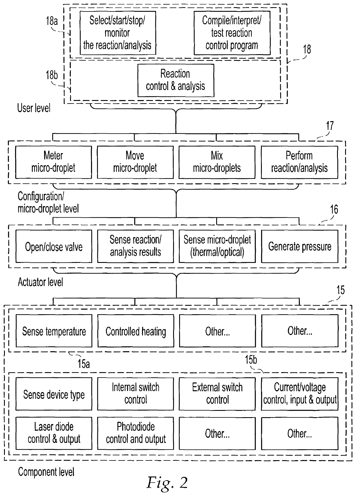
Section 5.1 generally describes preferred microfluidic devices controlled by the systems and methods of the present invention; section 5.2 describes preferred embodiments of these control systems and methods in view of the characteristics of preferred microfluidic devices; section 5.3 describes more preferred thermally-controlled microfluidic devices and their more preferred control systems and methods; furthermore, section 5.3 describes additional embodiments.

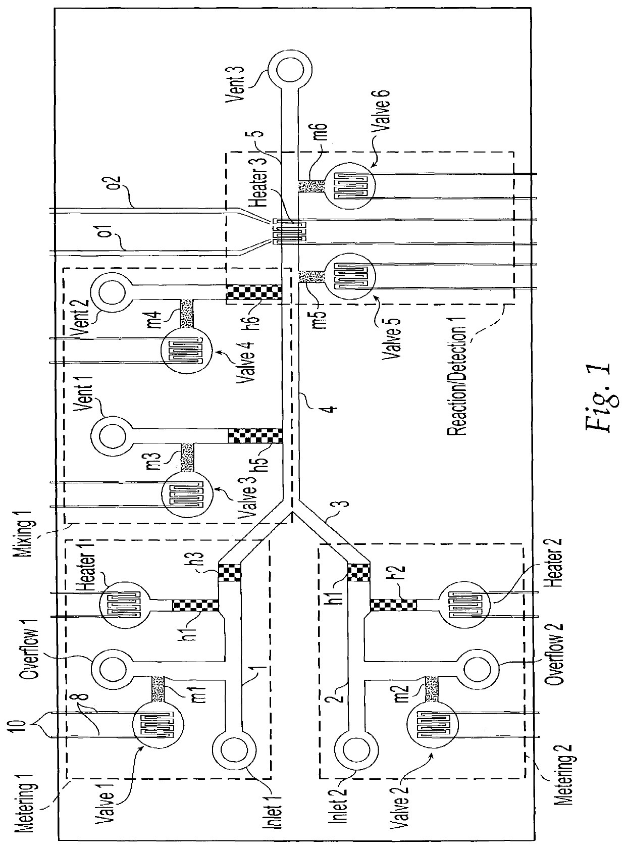
5.1. Microfluidic Processors and Control Systems

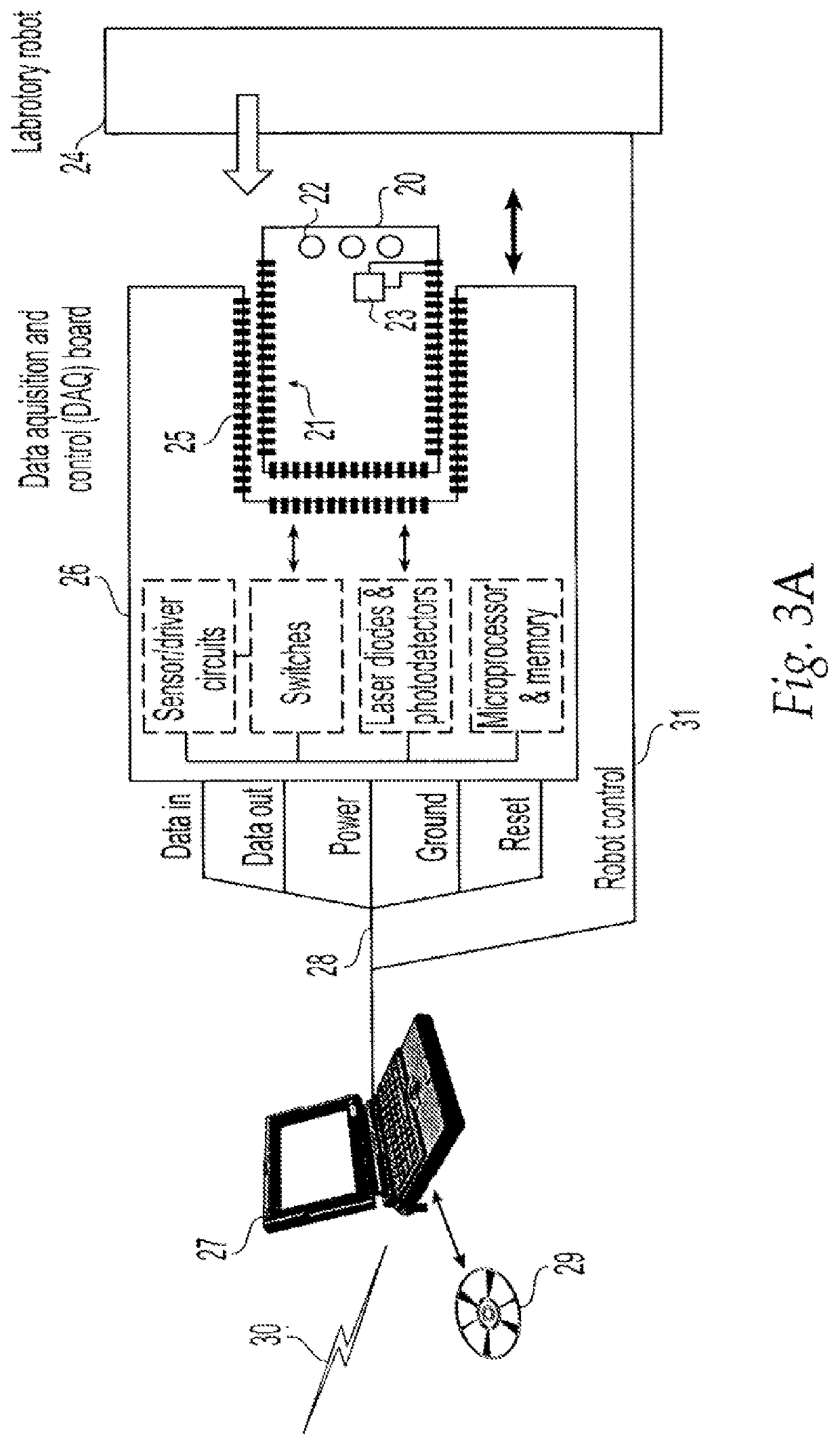
The control systems and methods of the present invention control microfluidic are preferably applied to microfluidic processors. In a preferred embodiment, the control systems and methods are configured to be able to control a plurality of differently configured and implemented microfluidic processors, and also to be able control a single, suitably-configured microfluidic processor to perform a range of different processes.

5.1.1. Microfluidic Processors

The term “microfluidic devi...


PUM

PropertyMeasurementUnit
sizesaaaaaaaaaa
sizesaaaaaaaaaa
linear dimensionsaaaaaaaaaa

Abstract

The present invention provides control methods, control systems, and control software for microfluidic devices that operate by moving discrete micro-droplets through a sequence of determined configurations. Such microfluidic devices are preferably constructed in a hierarchical and modular fashion which is reflected in the preferred structure of the provided methods and systems. In particular, the methods are structured into low-level device component control functions, middle-level actuator control functions, and high-level micro-droplet control functions. Advantageously, a microfluidic device may thereby be instructed to perform an intended reaction or analysis by invoking micro-droplet control function that perform intuitive tasks like measuring, mixing, heating, and so forth. The systems are preferably programmable and capable of accommodating microfluidic devices controlled by low voltages and constructed in standardized configurations. Advantageously, a single control system can thereby control numerous different reactions in numerous different microfluidic devices simply by loading different easily understood micro-droplet programs.

Description

1. FIELD OF THE INVENTIONThe present invention relates to the field of microfluidics. More particularly, the present invention is directed to control methods, control systems, and control software for microfluidic devices that operate by moving discrete micro-droplets through a sequence of determined configurations.2. BACKGROUND OF THE INVENTIONMicro / nano technology devices are known in the art as devices with components on the scale of 1 μm to 100 s of μm that cooperate to perform various desired functions. In particular, microfluidic devices are micro / nano technology devices that perform fluid handling functions, which, for example, cooperate to carry out a chemical or biochemical reaction or analysis.Most microfluidic devices in the prior art are based on fluid flowing through microscale passages and chambers, either continuously or in relatively large aliquots. Fluid flow is usually initiated and controlled by electro-osmotic and electrophoretic forces. See, e.g., U.S. Pat. No. ...

Claims


Application Information

Patent Timeline
Patent Type & Authority Patents(United States)
IPC IPC(8): G05D7/06B01L7/00G01N1/40G01N35/00G05B15/02B01L3/00B01F13/00B01J19/00G05B19/43
CPCG05D7/0617B01J19/0093B01F13/0071B01F13/0079B01L3/502784G05B15/02B01L2200/0673B01L2400/0442B01J2219/00889B01L2400/0487G01N35/00584B01J2219/00986B01L2200/147B01J2219/00831B01J2219/00837B01L7/52B01J2219/00873Y10T436/11G01N1/4077B01J2219/00833B01J2219/00936B01L2200/0605B01J2219/0086B01J2219/00828B01J2219/00945G05B2219/34198B01J2219/00783B01J2219/00891B01J2219/00943B01L2400/0677B01J2219/00862B01J2219/00835B01L2300/0816B01J2219/0097B01J2219/00961G05B19/43B01F33/3033B01F33/3021
Inventor HANDIQUE, KALYANGANESAN, KARTHIKBRAHMASANDRA, SUNDARESH N.
Owner HANDYLAB
Why Eureka
Eureka Blog
Learn More