Light source module

a technology of light source module and light source, which is applied in the direction of refractors, semiconductor devices, lighting and heating apparatus, etc., can solve the problems of increasing the components of the light source module, complicating assembly work, and limited light emission efficiency accordingly, and achieves easy assembly and high light emission efficiency.

Active Publication Date: 2020-03-03
LEOTEK CORP
View PDF15 Cites 0 Cited by
  • Summary
  • Abstract
  • Description
  • Claims
  • Application Information

AI Technical Summary

Benefits of technology

[0007]The invention provides a light source module that provides effects of high light emission efficiency and water-proofing and is easy to assemble.
[0023]In light of the above, in the light source module of the invention, the packing layer is filled between the LED package and the optical cover. The refractive index differences between the packing layer, the LED package and the optical cover of the light source module of the invention are less than the refractive index differences between the air layer, the LED package and the optical cover of the conventional light source module, so the light source module of the invention has better optical efficiency and light pattern control efficiency. Since an air gap does not exist between the LED package and the optical cover in the light source module of the invention, the loss resulting from light passing an interface between the encapsulant and an air layer and an interface between the air layer and the optical cover as in the conventional light source module can be prevented, which thereby improves light emission efficiency and improves lighting quality. In addition, the packing layer covers the LED package and provides water-proofing and dust-proofing effects. Moreover, it is not necessary to additionally use screws for fixture, which saves assembly time and work. Furthermore, if the diffuser particles are added in the packing layer, the light emitted by the LED package is homogenized and thereby provides users with comfortable visual effect and thus prevents glare.

Problems solved by technology

However, optical transmittance is suppressed by transmittance of the material itself and the Fresnel loss caused by an interface between air and the material, and light emission efficiency is limited accordingly.
Moreover, although the water-proofing effect can be achieved by additionally providing the water-proofing silicone layer and assembling with screws, these also increase components constituting the light source module and complicate the assembly work.

Method used


Image

  • Light source module
  • Light source module
  • Light source module

Examples


Embodiment Construction

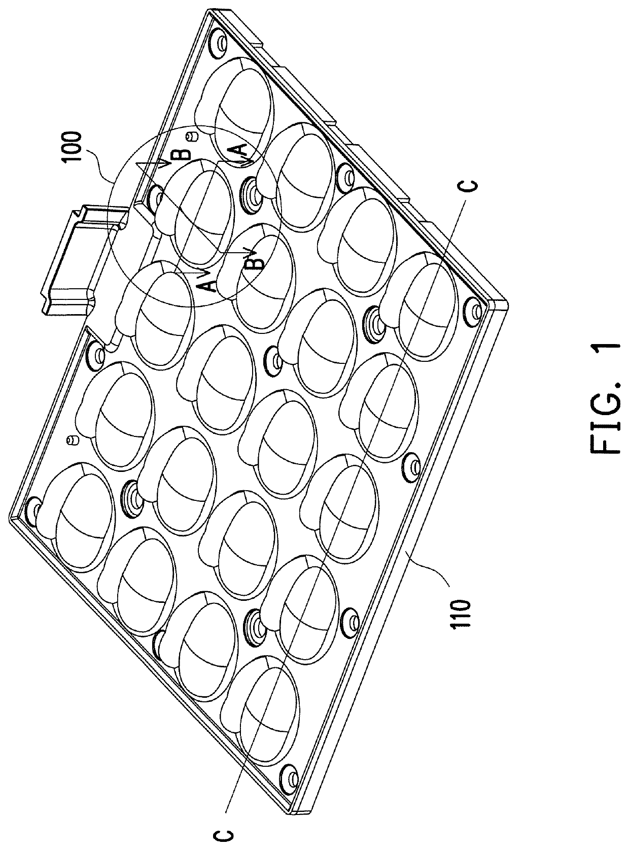
[0031]FIG. 1 is a schematic diagram illustrating a light source module according to an embodiment of the invention. Referring to FIG. 1, as an example, a plurality of light source modules 100 are arranged in a form of an array in FIG. 1 and are able to emit light in an array shape. Of course, in other embodiments, the light source modules 100 may be arranged in other forms and are not limited hereto. One of the light source modules 100 in FIG. 1 is taken as an example in the following to describe a structure of the light source module 100 in detail.

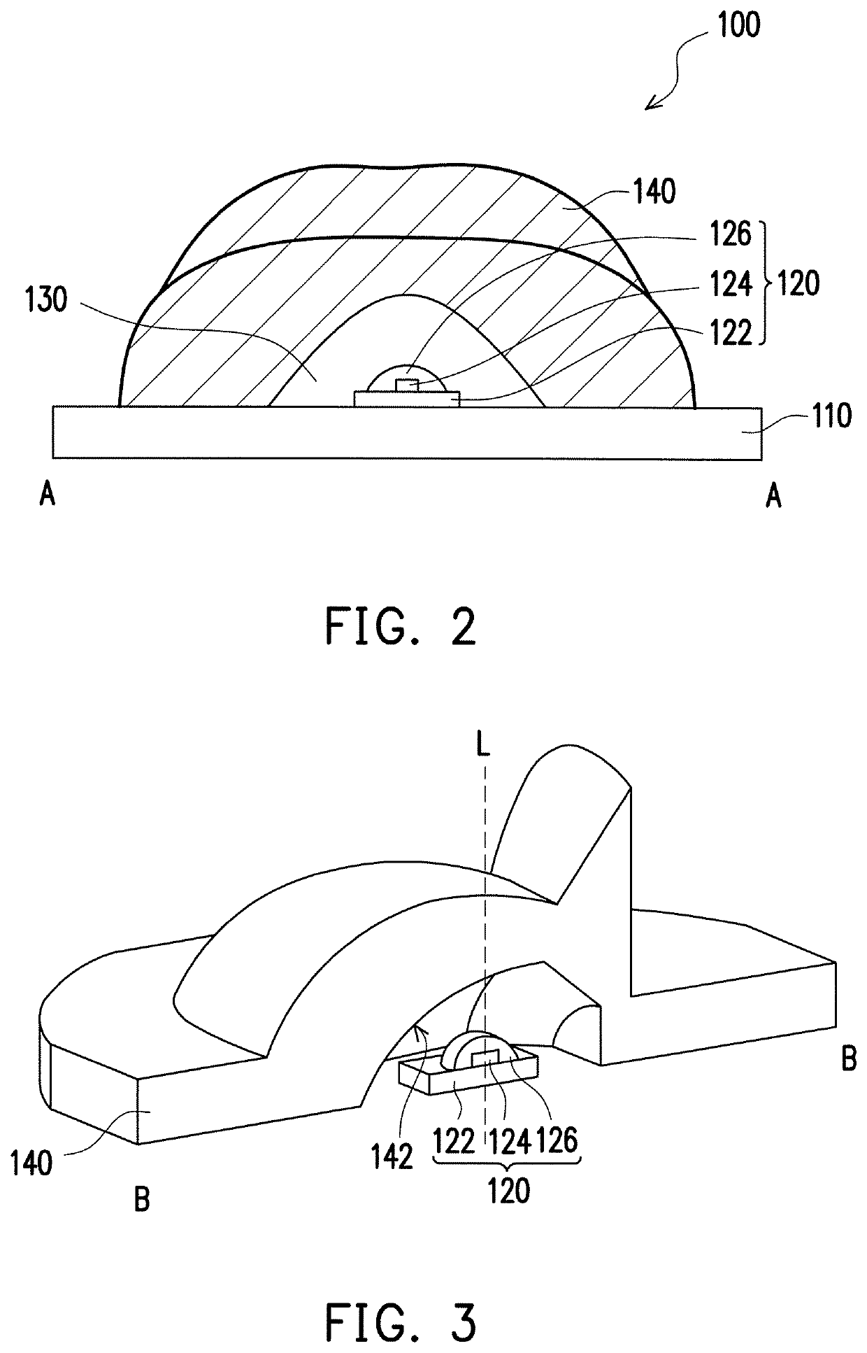
[0032]FIG. 2 is a cross-sectional schematic diagram along a line segment A-A of FIG. 1. Referring to FIG. 2, the light source module 100 of the present embodiment includes a substrate 110, an LED package 120, an optical cover 140, and at least one packing layer 130. In the present embodiment, the substrate 110 is any adequate circuit board such as an aluminum metal-core circuit board 110 on which a circuit (not illustrated) and an insulat...


PUM

PropertyMeasurementUnit
refractive indexaaaaaaaaaa
transmittanceaaaaaaaaaa

Abstract

A light source module including a substrate, an LED package, an optical cover, and at least one packing layer is provided. The LED package is disposed on the substrate and includes an encapsulant. The optical cover is disposed above the LED package. The at least one packing layer is filled between the LED package and the optical cover.

Description

CROSS REFERENCE TO RELATED APPLICATION[0001]This application claims the priority benefit of China application serial no. 201710416788.8, filed on Jun. 6, 2017. The entirety of the above-mentioned patent application is hereby incorporated by reference herein and made a part of specification.BACKGROUND OF THE INVENTION[0002]Field of the Invention[0003]The invention relates to a light source module, and in particular, a light source module that is water-proof and exhibits high light emission efficiency.[0004]Description of Related Art[0005]In the existing LED light source modules, an optical cover is mostly disposed at an outer side of an LED package, and an air layer exists between the LED package and the optical cover. The light pattern is adjusted through differences in refractive indexes and a curvature of the optical cover. Moreover, to satisfy the need for water-proofing, it is common to dispose an additional layer of water-proofing silicone between a substrate and the optical co...

Claims


Application Information

Patent Timeline
Patent Type & Authority Patents(United States)
IPC IPC(8): H01L33/56H01L33/54H01L33/60H01L33/58H01L33/48H01L33/50
CPCH01L33/54H01L33/505H01L33/507H01L33/56H01L33/502H01L33/58H01L33/483H01L33/60H01L2933/0091H01L33/486H01L2933/0058H01L2933/005H01L2933/0041F21V3/00F21V5/00F21V7/10
Inventor PENG, YAO-CHICHIU, TSAN-LILI, PO-CHANGCHIEN, MING-HUNG
Owner LEOTEK CORP
Why Eureka
Try Eureka