

Apparatus and methods for mirror tunnel imaging device and for providing pseudobessel beams in a miniaturized optical system for imaging
a mirror tunnel and imaging device technology, applied in the field of imaging apparatus and devices, can solve the problems of limited performance, difficulty in application of in-vivo imaging techniques, and limited depth of focus, so as to increase the depth of focus and increase the focusing range
- Summary
- Abstract
- Description
- Claims
- Application Information
AI Technical Summary
Benefits of technology
Problems solved by technology
Method used
Image

Examples
Embodiment Construction
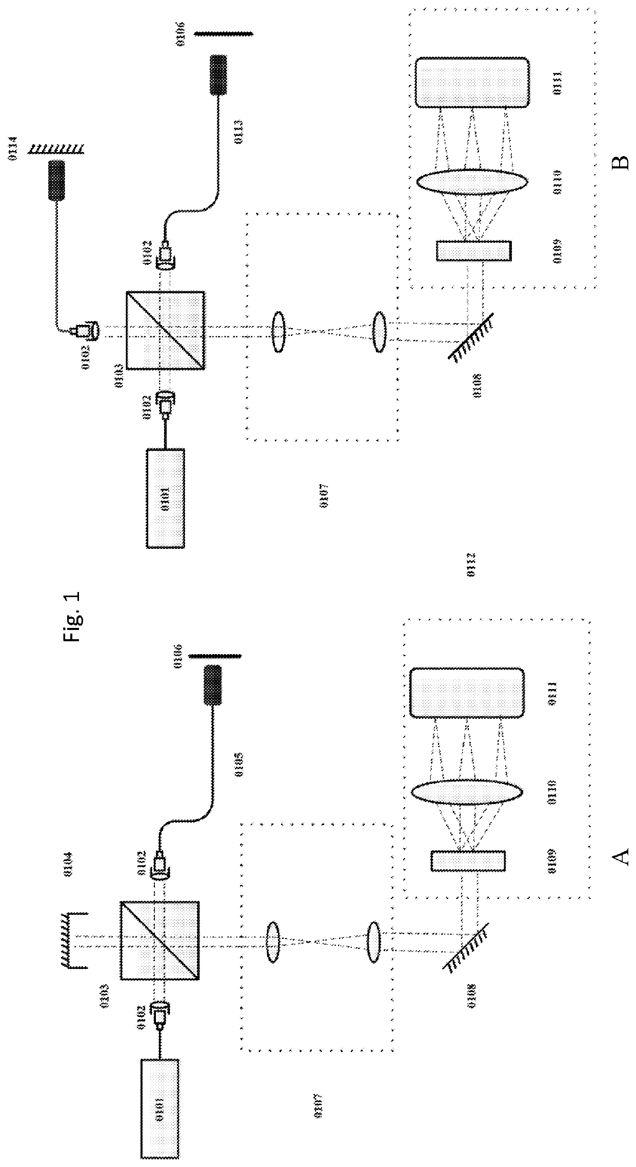
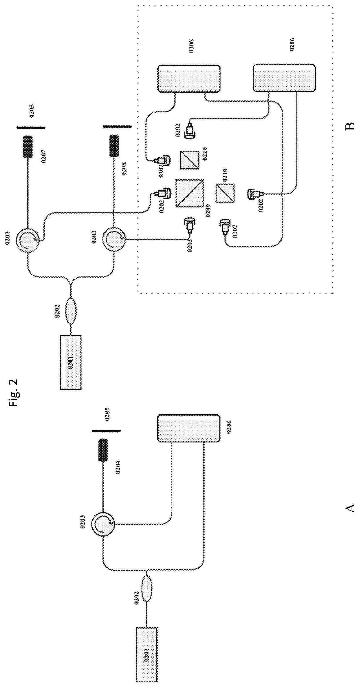
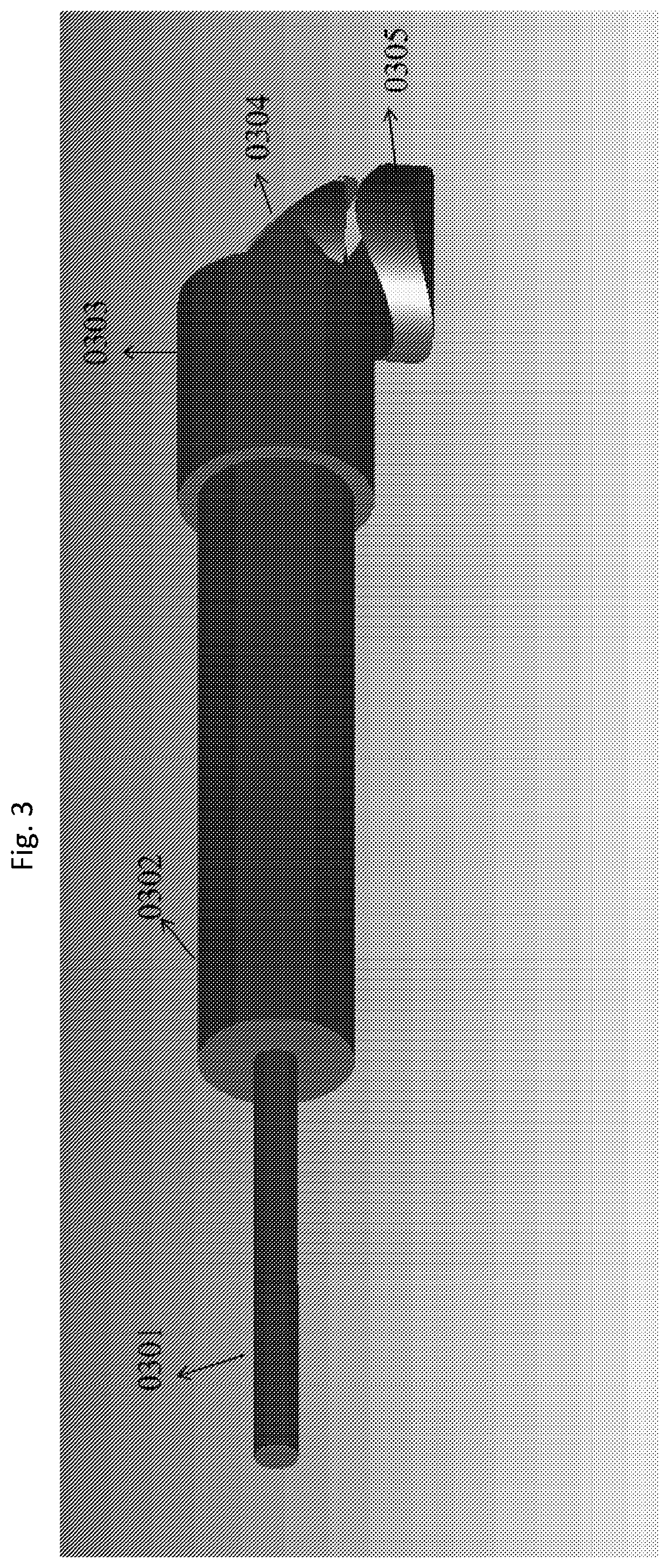
[0009]To that end, to solve the problem of limited depth of focus of high-resolution objective optics in OCT imaging, according to an exemplary embodiment of the present disclosure, it is possible to provide a mirror tunnel based focusing optical system that can significantly increase focusing range. According to certain exemplary embodiment of the present disclosure, term mirror tunnel can be referred to as, e.g., a cylindrical waveguide that transmits light of different propagation modes; after focusing, multiple on-axis foci are introduced to extend the depth of focus. The self-imaging effect of cylindrical waveguide can divide the wavefront into multiple annular zones, collinear beams are generated and focused onto different depth region in image space. Therefore, this can be referred to as, e.g., a self-imaging wavefront division technique. In other exemplary embodiments of the present disclosure, the exemplary mirror tunnel can have other geometries, such as an elliptical wave...
PUM
 Abstract
Description
Claims
Application Information