
Bar-type screen cage

a bar-type and cage technology, applied in the direction of screening, stationary filter element filtering, screening, etc., can solve the problems of high cost and difficulty in reliably reproducing predetermined slot widths, and all currently known configurations of bar-type screen cages are very cost-intensive, and achieve the effect of high stability and durable connection

Active Publication Date: 2020-03-17
ANDRITZ FIEDLER
View PDF21 Cites 0 Cited by
  • Summary
  • Abstract
  • Description
  • Claims
  • Application Information

AI Technical Summary

Benefits of technology

This patent is about a new way to make a screen cage for barcodes. The new method uses a support arrangement with resistance welding to secure the screen bars in place. This arrangement includes support wires that are narrowly spaced apart, creating a stable slot width. Additional welding seams are used to connect the support wires with each other and the screen bars, making a durable and stable connection. Reinforcement rings can also be added to increase the stability of the screen cage. Overall, this new method allows for a cost-effective and reliable production of bar-type screen cages.

Problems solved by technology

All currently known configurations of bar-type screen cages are very cost-intensive and it is in particular difficult to reliably reproduce predetermined slot widths.

Method used


Image

  • Bar-type screen cage
  • Bar-type screen cage
  • Bar-type screen cage

Examples


Embodiment Construction

[0024]In the Figures of the drawing same or similar parts are provided with the same reference numerals.

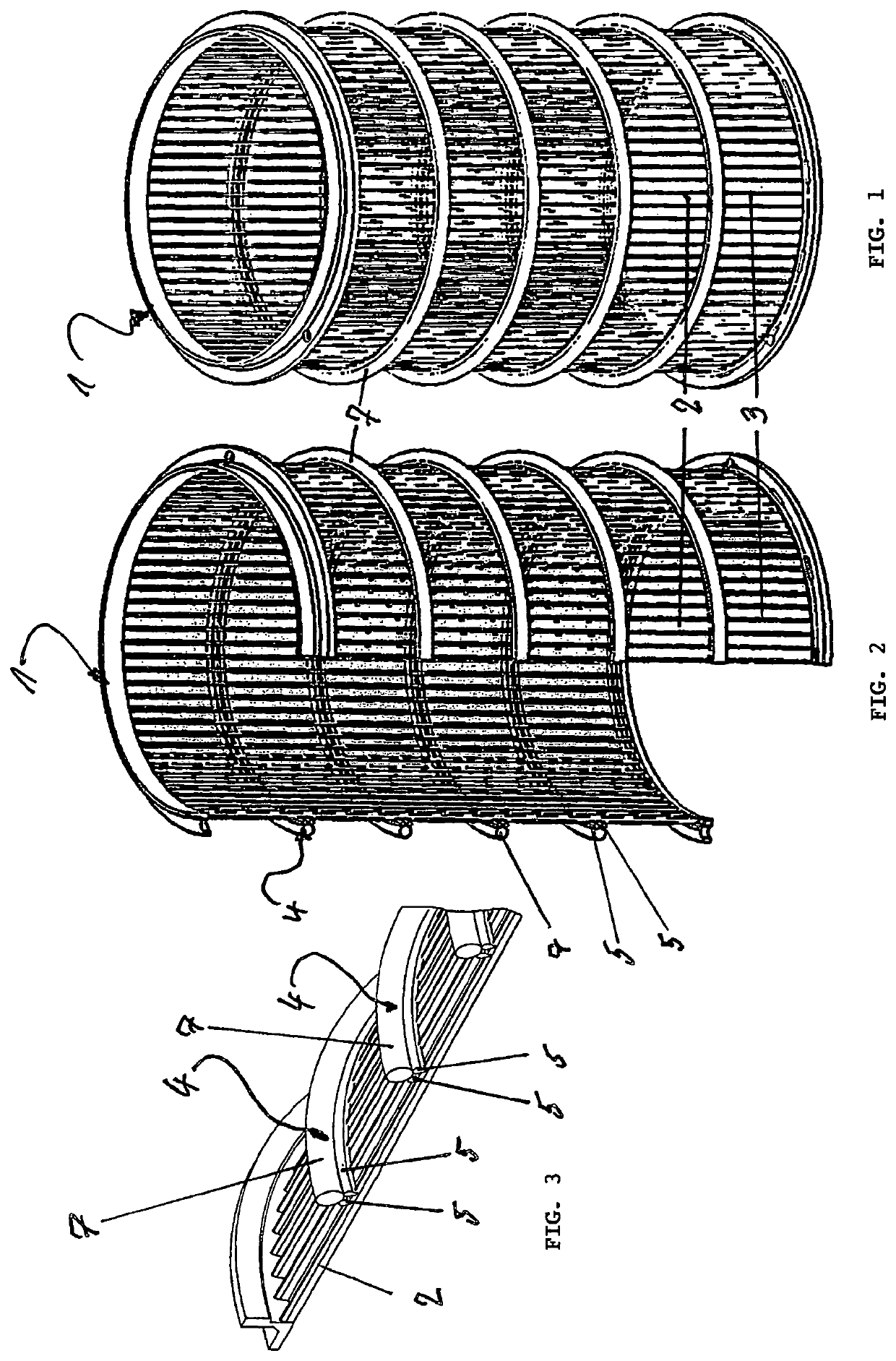
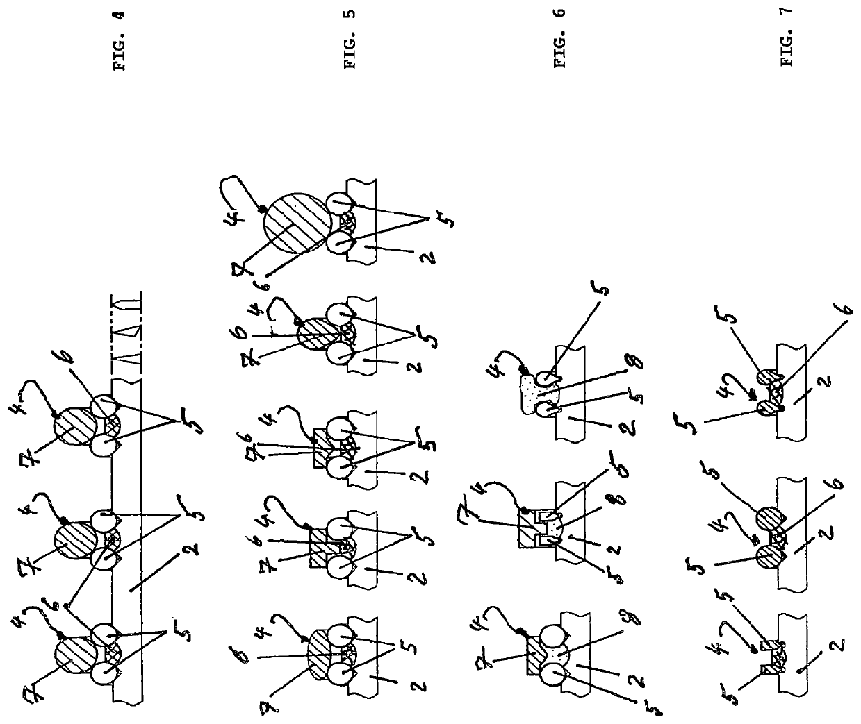
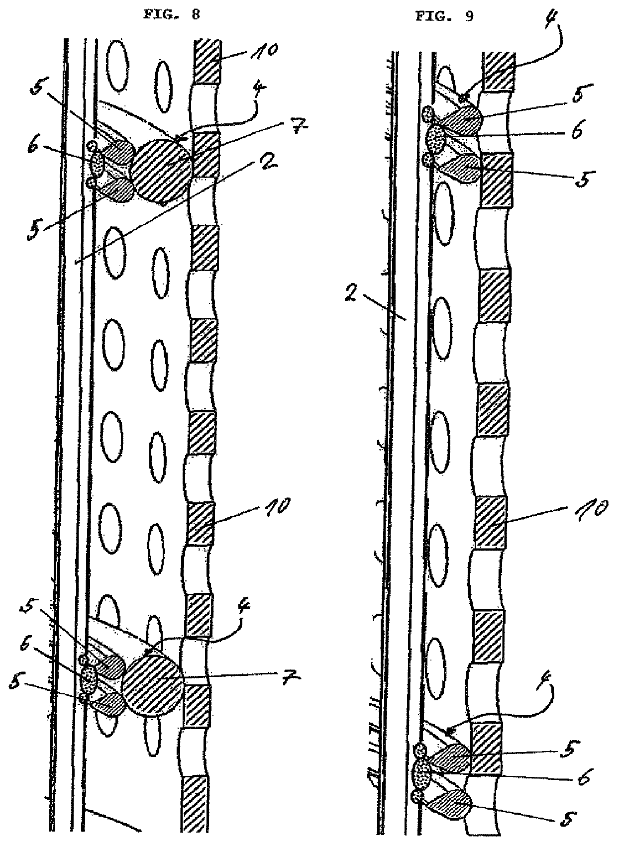
[0025]FIGS. 1 and 2 show a screen cage, overall designated with reference numeral 1, which has circumferentially spaced apart profiled screen bars (profile bars) 2, with screen slots 3 having a predetermined slot width being delimited between the screen bars. The screen cage 1 further includes multiple support arrangements, designated with reference numeral 4, which are spaced apart in axial direction of the screen cage 1 and are fastened on the outside on the screen bars 2 by means of welding. As can be seen in particular in FIG. 3 as enlarged section of the perspective views of FIGS. 1 and 2, each support arrangement 4 includes at least two support wires 5 that are spaced apart in axial direction of the screen bars 2. These support wires 5 are fastened on the screen bars by means of resistance welding. An additional welding seam, designated with reference numeral 6, is provided ...


PUM

PropertyMeasurementUnit
distanceaaaaaaaaaa
distanceaaaaaaaaaa
distanceaaaaaaaaaa

Abstract

A bar-type screen cage has profiled screen bars which are spaced apart in a circumferential direction. Multiple support arrangements which are spaced apart in an axial direction of the screen cage are fastened by welding to the profile bars at the outside. The screen bars, which are spaced apart in an axial direction, form screen slots between them. Each support arrangement includes at least two support wires which are closely spaced apart in the axial direction of the screen bars and which are fixed to the screen bars by resistance welding. The two support wires of each support arrangement and the profile bars-are fixedly connected to one another by way of an additional weld seam.

Description

CROSS-REFERENCES TO RELATED APPLICATIONS[0001]This application is the U.S. National Stage of International Application No. PCT / EP2016 / 000327, filed Feb. 25, 2016, which designated the United States and has been published as International Publication No. WO 2016 / 142035 and which claims the priority of German Patent Application, Serial No. 10 2015 003 020.5, filed Mar. 6, 2015, pursuant to 35 U.S.C. 119(a)-(d).BACKGROUND OF THE INVENTION[0002]The invention relates to a bar-type screen cage with profiled screen bars (profile bars) which are spaced apart in circumferential direction so as to form screen slots, wherein on the outside multiple support arrangements, which are spaced apart in axial direction, are fastened by means of welding, which support arrangements can for example be formed by support wires or support rings. Such a bar-type screen cage is known from WO 02 / 097 190 A1.[0003]From EP 0 958 432 B1 a wire screen product, such as a screen plate or a screen cage is known, which...

Claims


Application Information

Patent Timeline
Patent Type & Authority Patents(United States)
IPC IPC(8): B01D29/11B01D29/44B01D29/35D21D5/16B07B1/18B07B1/46
CPCB01D29/111B01D29/35D21D5/16B07B1/469B07B1/4618B01D29/445B07B1/18
Inventor MICKELAT, THOMASREINSTEIN, MICHAEL
Owner ANDRITZ FIEDLER
Learn More