Separator plate for an electrochemical system

a technology of electrochemical system and separation plate, which is applied in the direction of electrochemical generators, fuel cells, electrical apparatus, etc., can solve the problems of reducing the mechanical stability and elasticity of the bead arrangement, and achieve the best possible mechanical stability and compactness

Active Publication Date: 2020-03-24
REINZ DICHTUNGS
View PDF15 Cites 0 Cited by
  • Summary
  • Abstract
  • Description
  • Claims
  • Application Information

AI Technical Summary

Benefits of technology

[0008]The object of the present invention is therefore to create a separator plate for an electrochemical system, which separator plate has the best possible mechanical stability and compactness and ensures the most efficient possible media supply of the system.

Problems solved by technology

However, the openings in the bead flanks necessarily bring about a reduction of the mechanical stability and elasticity of the bead arrangement.

Method used


Image

  • Separator plate for an electrochemical system
  • Separator plate for an electrochemical system
  • Separator plate for an electrochemical system

Examples


Embodiment Construction

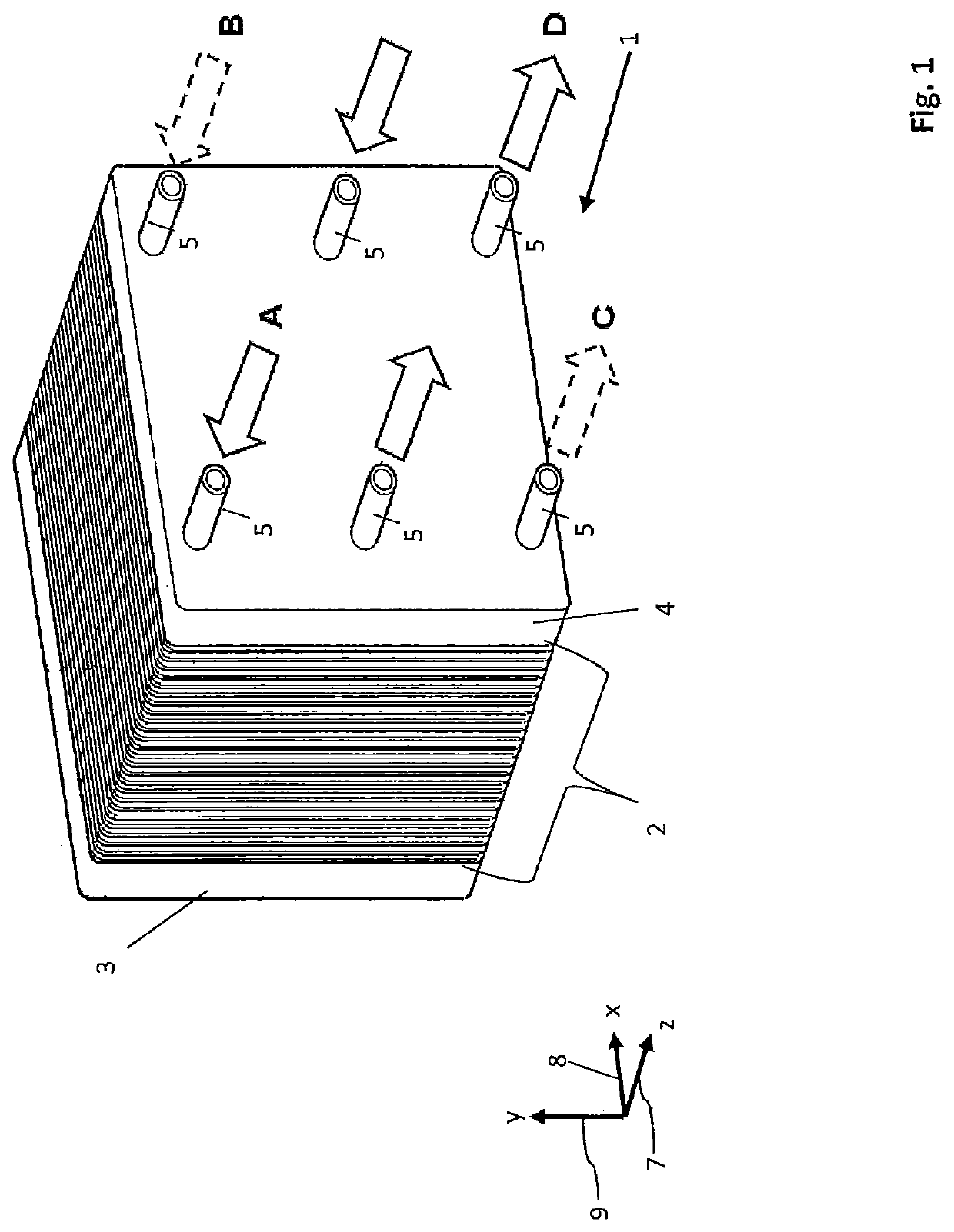
[0053]FIG. 1 shows an electrochemical system 1 according to the invention, comprising a stack 2 of separator plates of identical design, which are stacked along a z-direction 7 and are clamped between two end plates 3, 4. The separator plates are formed here as bipolar plates and each comprise two individual plates connected to one another. In the present example, the system 1 is a fuel cell system. Each two adjacent bipolar plates of the stack 2 thus enclose therebetween an electrochemical cell designed to convert chemical energy into electrical energy. In alternative embodiments the system 1 can also be formed as an electrolyser, electrochemical compressor, or as a humidifier for a fuel cell system. Separator plates are likewise used in those electrochemical systems. The structure of these separator plates corresponds to the structure of the bipolar plates explained here in greater detail, even if the media guided, on or through the separator plates differ.

[0054]The z-axis 7, toge...


PUM

PropertyMeasurementUnit
thicknessaaaaaaaaaa
thicknessaaaaaaaaaa
heightaaaaaaaaaa

Abstract

A separator plate for an electrochemical system has at least one passage opening for forming a media channel for feeding or discharging media. At least one bead arrangement arranged around the at least one passage opening, for the purpose of sealing the passage opening is provided. At least one of the flanks of the bead arrangement has at least one opening for conducting a medium through the bead flank. At least one guide channel is connected, on an exterior of the bead arrangement, to the openings in the bead flank and is fluidically connected to a bead interior via the opening in the bead flank. The guide channel is designed such that a guide channel height perpendicularly to the flat surface plane of the separator plate increases at least in some sections in the direction of said bead arrangement.

Description

BACKGROUND OF THE INVENTION[0001]The invention relates to a separator plate for an electrochemical system. For example, the electrochemical system can be a fuel cell system, an electrochemical compressor, a humidifier for a fuel cell system, or an electrolyser.[0002]Known electrochemical systems usually comprise multiple separator plates, which are arranged in a stack, so that every two adjacent separator plates enclose an electrochemical cell or a humidifier cell. The separator plates usually each comprise two individual plates, which are connected to one another along their rear sides facing away from the electrochemical cells or dehumidifier cells. For example, the separator plates can be used in order to electrically contact the electrodes of the individual electrochemical cells (for example fuel cells) and / or to electrically connect adjacent cells (series connection of the cells). The separator plates can also be used to dissipate heat produced in the cells between the separato...

Claims


Application Information

Patent Timeline
Patent Type & Authority Patents(United States)
IPC IPC(8): H01M8/0254H01M8/0206H01M8/247H01M8/0271H01M8/0265H01M8/0267
CPCH01M8/247H01M8/0271H01M8/0254H01M8/0206H01M8/0267H01M8/0265Y02E60/50
Inventor KUNZ, CLAUDIAWENZEL, STEPHAN
Owner REINZ DICHTUNGS
Why Eureka
Try Eureka