[0012]A significant
advantage of the present invention is that the
calcium magnesium aluminosilicate glass
coating assists in lowering the
sintering and hot-isostatic-pressing temperatures to 800° C. This lower temperature eliminates the need to use expensive
platinum,
palladium, or
palladium-silver
alloy as the terminal
metal. In fact, this temperature is in a safe range that allows
nickel to be used, providing a major cost saving in material expense and also
power usage during the hot-isostatic-pressing process. Also, since the glass becomes easily deformable and flowable at these temperatures it will assist in removing the voids from the EESU material during the hot-isostatic-pressing process. The manufacturer of such systems is Flow
Autoclave Systems, Inc. For this product to be successful it is mandatory that all voids be removed to assist in ensuring that the
high voltage breakdown can be obtained. Also, the method described in this patent of coating the
calcium magnesium aluminosilicate glass ensures that the hot-isostatic-pressed double-coated composition-modified
barium titanate high-relative-
permittivity layer is uniform and homogeneous.
[0013]Yet another aspect of the present invention is that each component of the EESU is produced by screen-printing multiple
layers of
nickel electrodes with screening ink from nickel powder. Interleaved between nickel electrodes are
dielectric layers with screening ink from calcined double-coated high-permittivity calcined composition-modified
barium titanate powder. A unique independent dual screen-printing and layer-
drying system is used for this procedure. Each screening ink contains appropriate plastic resins, surfactants, lubricants, and solvents, resulting in a proper
rheology for
screen printing. The number of these
layers can vary depending on the
electrical energy storage requirements. Each layer is dried before the next layer is screen printed. Each
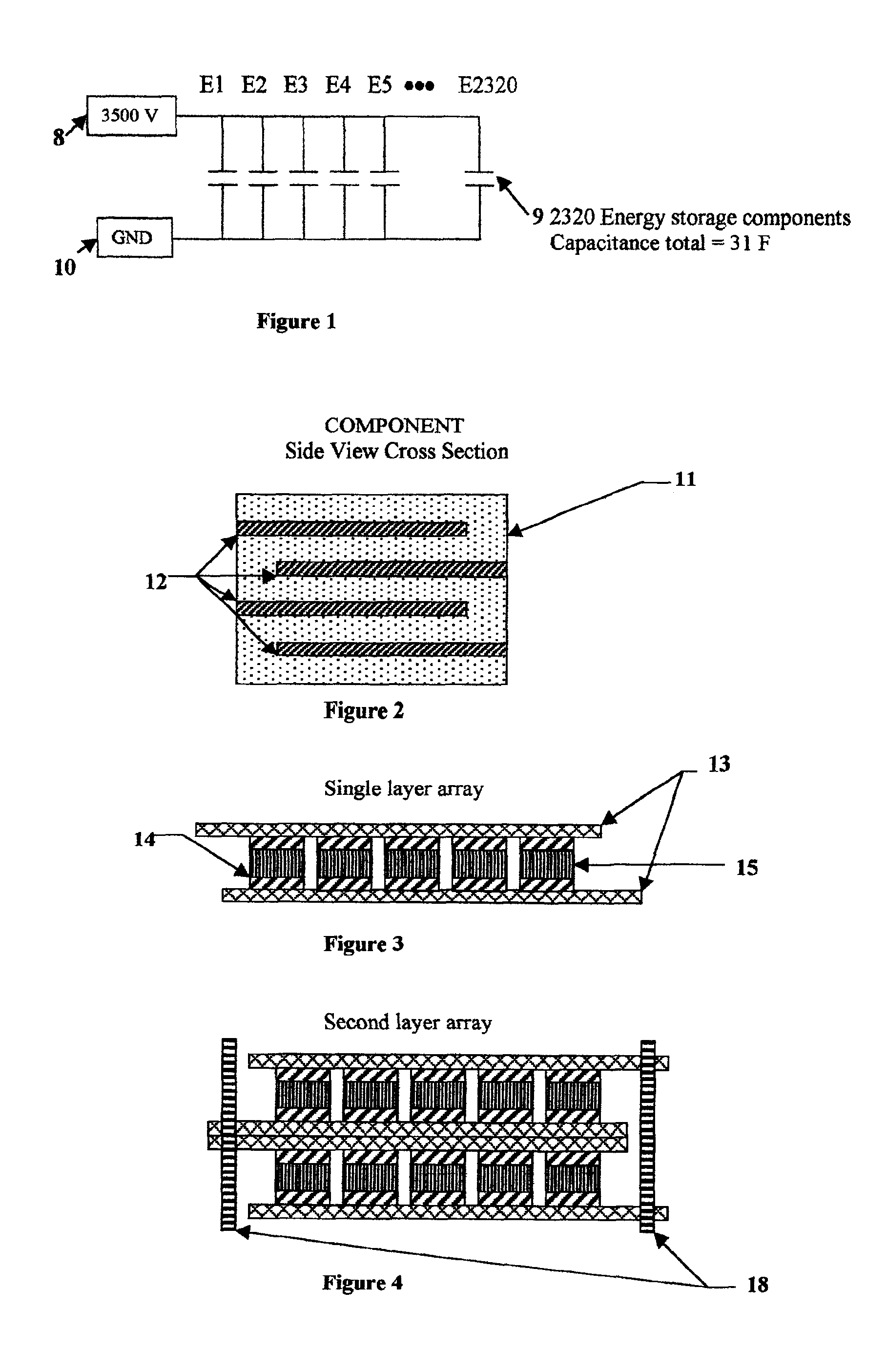
nickel electrode layer 12 is alternately preferentially aligned to each of two opposite sides of the component automatically during this process as indicated in FIG. 2. These layers are screen printed on top of one another in a continuous manner. When the specified number of layers is achieved, the component layers are then baked to obtain by further
drying sufficient handling strength of the green plastic body. Then the array is
cut into individual components to the specified sizes.
[0014]Alternatively, the
dielectric powder is prepared by blending with plastic binders, surfactants, lubricants, and solvents to obtain a
slurry with the proper
rheology for
tape casting. In
tape casting, the powder-binder mixture is extruded by pressure through a narrow slit of appropriate aperture height for the thickness desired of the green plastic ceramic layer onto a moving plastic-tape carrier, known as a doctor-blade web coater. After
drying to develop sufficient handling strength of the green plastic ceramic layer this layer is peeled away from the plastic-tape carrier. The green plastic ceramic layer is
cut into sheets to fit the screen-printing frame in which the
electrode pattern is applied with nickel ink. After drying of the
electrode pattern, the sheets are stacked and then pressed together to assure a well-bonded lamination. The laminate is then
cut into components of the desired shape and size.
[0015]The components are treated for the binder-
burnout and
sintering steps. The
furnace temperature is slowly ramped up to 350° C. and held for a specified length of time. This heating is accomplished over a period of several hours so as to avoid any
cracking and
delamination of the body. Then the temperature is ramped up to 850° C. and held for a specified length of time. After this process is completed the components are then properly prepared for the
hot isostatic pressing at 700° C. and the specified pressure. This process will eliminate voids. After this process the components are then side lapped on the connection side to
expose the preferentially aligned nickel electrodes 12. Then these sides are dipped into ink from nickel powder that has been prepared to have the desired
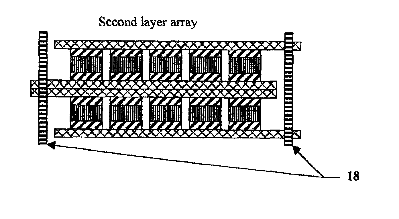
rheology. Then side conductors of nickel 14 are dipped into the same ink and then are clamped onto each side of the components 15 that have been dipped into the nickel powder ink. The components are then fired at 800° C. for 20 minutes to bond the nickel bars to the components as indicated in FIG. 3. The components are then assembled into a first-level array, FIG. 3, with the use of the proper tooling and solder-bump technology. Then the first-level arrays are assembled into a second-level array, FIG. 4, by stacking the first array layers on top of one another in a preferential mode. Then nickel bars 18 are attached on each side of the second array as indicated in FIG. 4. Then the EESU is packaged into its final
assembly.
[0016]The features of this patent indicate that the ceramic EESU, as indicated in Table 1, outperforms the electrochemical battery in every parameter. This technology will provide mission-critical capability to many sections of the energy-storage industry.
[0017]TABLE 1The parameters of each technology to store 52.2 kW · h of electricalenergy are indicated-(data as of February 2001 from manufacturers'specification sheets).CeramicNiMHLA(Gel)EESUNi—ZWeight (pounds) 1716 3646 336 1920Volume (inch3)17,88143,045200534,780
Discharge rate5% / 301% / 300.1% / 301% / 30daysdaysdaysdaysCharging time (full)1.5 hr8.0 hr3-6 min1.5 hrLife reduced withmoderatehighnonemoderatedeep cycle useHazardous materialsYESYESNONEYES


