Angled multi-contact connector and assembly method thereof

a multi-contact, connector technology, applied in the direction of contact member assembly/disassembly, electrically conductive connections, coupling device connections, etc., can solve the problems of non-negligible additional cost linked to the production of hinges, unsatisfactory clipping solutions, and difficult operation of operative assembly of connectors

Active Publication Date: 2020-03-24
RAYDIALL
View PDF21 Cites 0 Cited by
  • Summary
  • Abstract
  • Description
  • Claims
  • Application Information

AI Technical Summary

Benefits of technology

[0006]The patent application EP 2603953A1 proposes an analogous solution with parts that are folded over but these are mounted directly on the insulator on hinges and are folded over to trap the contacts, in order to immobilize them but also to insulate them from one another, the front portions of the contacts being first inserted longitudinally via the rear end of the body into through-openings forming housings. This solution implies a non-negligible additional cost linked to the production of the hinges, which may moreover be relatively fragile.
[0052]The method according to the invention may be particularly simple and quick to use because the contacts are mounted from the rear by accommodating their front end in the openings passing through the insulator and the single part providing the physical separation between contacts and from the outside and therefore the shielding conductive cap is fitted by inserting it in and clipping in the insulator.

Problems solved by technology

This clipping solution is unsatisfactory because in the event of incorrect clipping of one or other of the contacts a short circuit may occur with the shielding conductive body arranged around the insulator.
A disadvantage of this solution is that it is not easy for an operative assembling the connector to hold the tongues simultaneously in their bent over position for the time it takes to fit the shielding conductive body around them.
This solution implies a non-negligible additional cost linked to the production of the hinges, which may moreover be relatively fragile.
The solutions disclosed by the applications EP 2915218A1 and EP 2603953A1 moreover imply a necessarily limited choice of insulating material for the production of the tongues that can be bent over or hinged parts that can be folded over and a non-negligible production cost.

Method used


Image

  • Angled multi-contact connector and assembly method thereof
  • Angled multi-contact connector and assembly method thereof
  • Angled multi-contact connector and assembly method thereof

Examples


Embodiment Construction

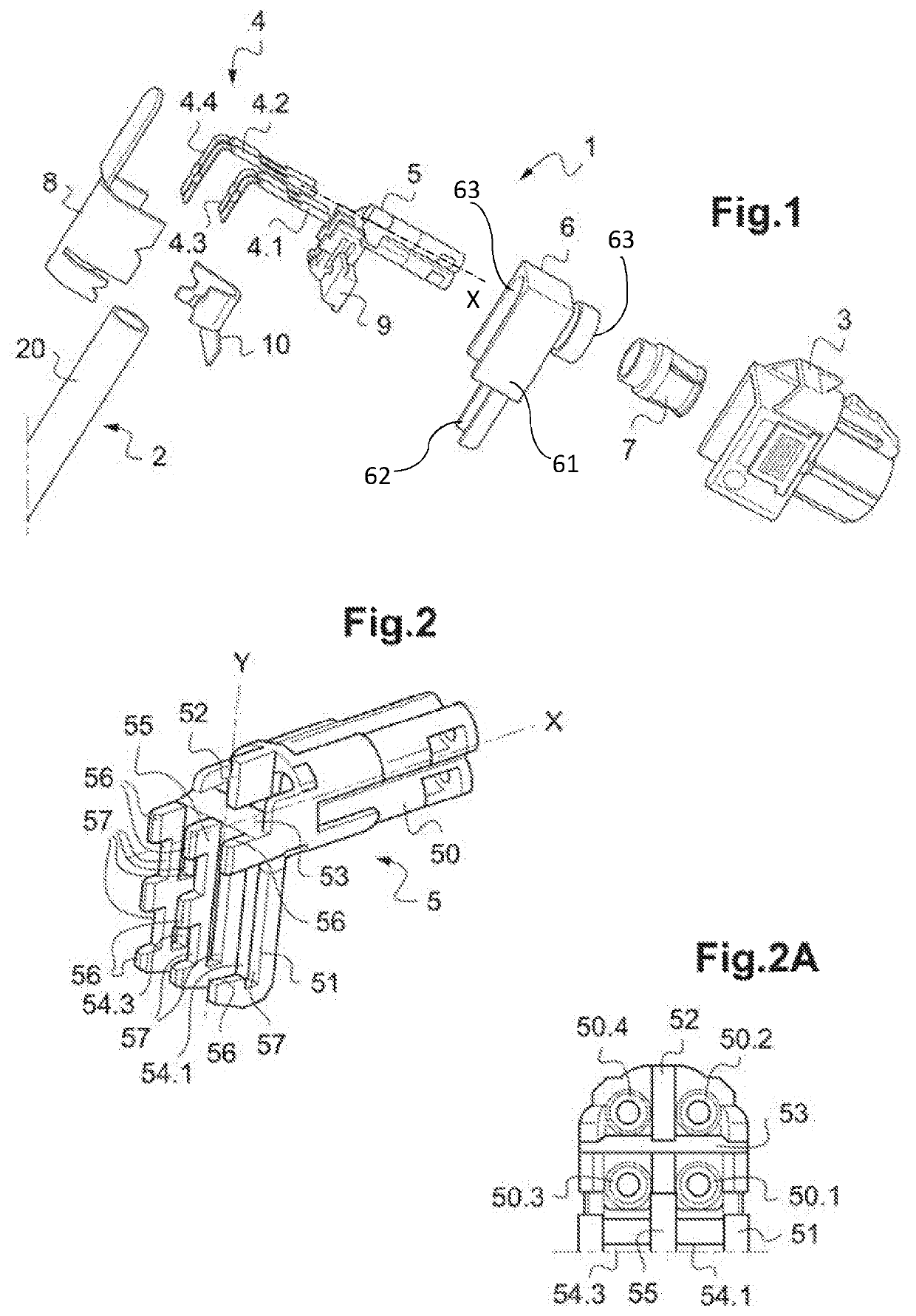
[0066]There has been represented in FIG. 1 a connection system incorporating an angled multicontact connector 1 according to one embodiment of the invention.

[0067]In the example described, this system includes the angled connector 1 according to the invention and a plastic material housing 3 on which it is mounted.

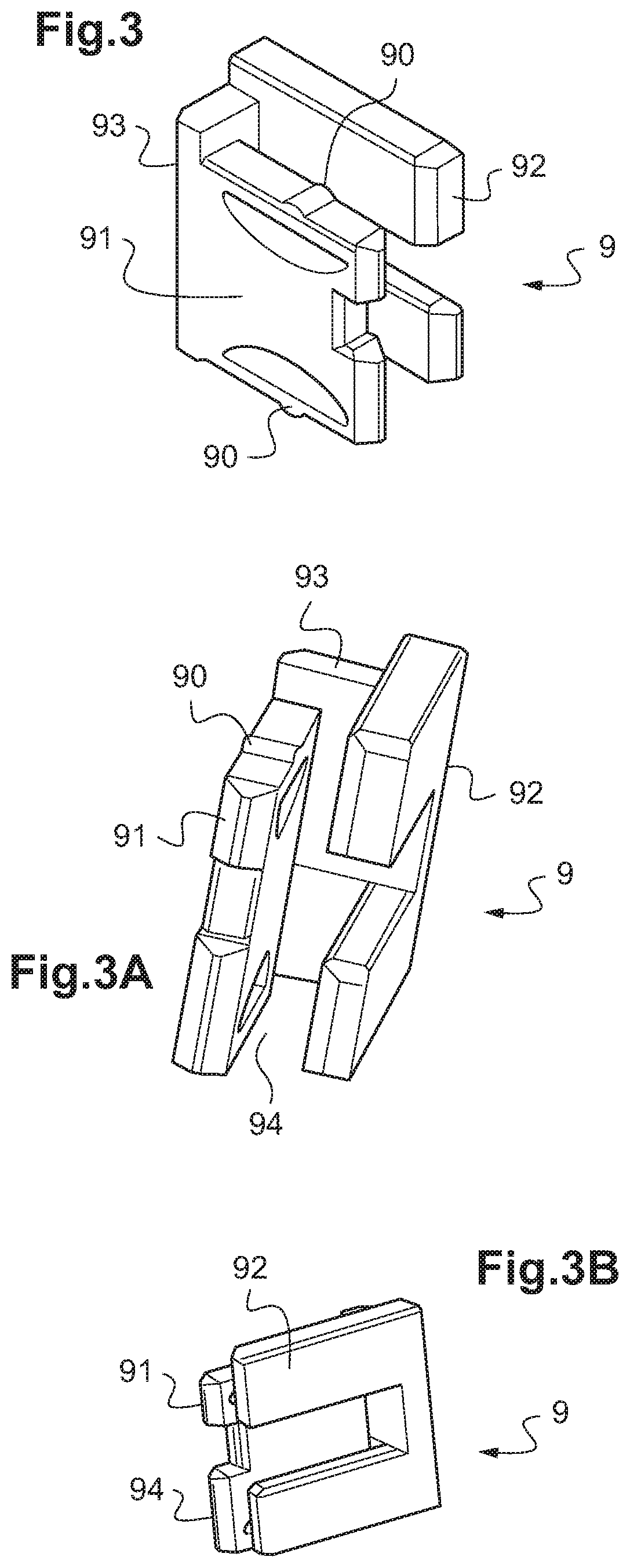
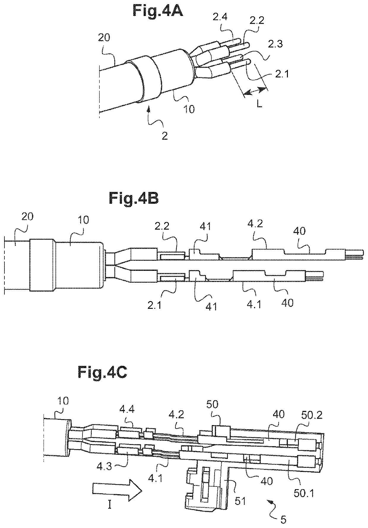
[0068]As shown, the angled connector 1 according to the invention includes an assembly 4 including four contacts 4.1, 4.2, 4.3, 4.4, an angled insulator 5 accommodating the contacts, an insulating part 9 inserted in and clipped into the angled insulator 5, a conductive body 6 accommodating the angled insulator 5 and the insulating part 9, an earth contact 7 closed on itself fixed to the conductive body 6, and a conductive material cap 8 adapted to close the conductive body 6.

[0069]The angled insulator 5 may also be described as an insulative angled body.

[0070]As described hereinafter, each of the contacts 4.1 to 4.4 of the angled connector 1 is crimped to a conductor 2.1 t...


PUM


Abstract

An angled multicontact connector comprises at least two angled contacts, an insulative angled body made of an insulative material, a conductive angled body made of a conductive material, a conductive material cap adapted to be fixed to the cable and to close the conductive angled body around the angled contacts. The insulative angled body includes at least one groove open toward the outside, each groove being adapted to receive at least in part the rear end of one of the angled contacts. The angled multicontact connector further includes an insulative material part adapted to be removably fixed to the insulative angled body to retain the rear end of the angled contacts not received in a groove and to separate each rear end from the rear end of any other angled contact, and from the conductive cap when the conductive cap is in a position closing the conductive angled body.

Description

INTRODUCTION[0001]The present invention concerns an angled electrical connector of the multicontact type intended to be mounted on a cable including a plurality of insulated conductors, a connection system including a connector of this kind, and an associated assembly method.[0002]The connector according to the invention is advantageously an RF connector, i.e. able to transmit signals in the range from direct current (DC) to radiofrequencies (RF), including microwave frequencies (HF), the signals being high speed data link (HSDL) digital signals or RF signals.[0003]The invention more particularly concerns angled multicontact connectors intended to be mounted on cables with insulated conductors of differential pair type comprising four conductors or more per differential pair.[0004]The patent EP 1825575B1 discloses an angled multicontact connector including an electrical insulator in which each of four central contacts is mounted by clipping it into a groove in the body, clipping bei...

Claims


Application Information

Patent Timeline
Patent Type & Authority Patents(United States)
IPC IPC(8): H01R13/502H01R13/436H01R4/18H01R43/20H01R24/28H01R13/506H01R9/03
CPCH01R43/20H01R13/4361H01R4/18H01R24/28H01R13/502H01R13/506H01R9/03H01R13/025H01R13/516H01R13/646H01R13/648
Inventor GABET, DENISANNEQUIN, SEBASTIEN
Owner RAYDIALL
Why Eureka
Try Eureka