Prosthesis Removal Cutting Guide, Cutting Tool and Method

a cutting guide and prosthesis technology, applied in the field of orthopaedics, can solve the problems of difficult removal of the prosthesis from the bone, the difficulty of total joint arthroplasty, and the osteoarthritis or rheumatoid arthritis of joint replacement surgery, so as to reduce the damage of the tool, reduce the damage, and reduce the effect of bone removal

Inactive Publication Date: 2011-08-25
DEPUY SYNTHES PROD INC
View PDF101 Cites 0 Cited by
  • Summary
  • Abstract
  • Description
  • Claims
  • Application Information

AI Technical Summary

Benefits of technology

[0018]Another technical advantage of the present invention reduces damage to the tool caused by the tool being in contact in cutting the hardened prosthesis. For example, according to one aspect of the present invention the tool includes channels, which guide the tool in a spaced apart relationship to the prosthesis.
[0019]Further, according to a another aspect of the present invention, the guide includes a first guide feature which cooperates with a prosthesis feature such that the guide and the prosthesis are aligned such that the movement of the tool along the channels provides for an accurate space from the prosthesis cut such that the tool does not contact the prosthesis and cause damage to the tool.
[0020]A further technical advantage of the present invention includes reduced damage and minimal removal of bone during the removal cuts performed by the tool. For example, according to one aspect of the present invention, the guide includes channels which may be aligned with the periphery of the tool and the guide, has a feature which may be aligned with a feature on the prosthesis such that if the tool is moved about the channels of the guide the cutting tool accurately cuts a minimal path adjacent to the prosthesis such that the amount of bone loss during prosthesis removal is minimized.
[0021]The technical advantages of the present invention further include the ability to form the removal cuts to remove the implant in a much greater speed. For example, according to one aspect of the present invention, the guide includes a plurality of spaced-apart channels which occupy most of the cross sectional area of the guide such that when the guide, in cooperation with the tool, is used to form the pockets for the implant, only a quick and simple use of an osteotome to remove the small portions of the material remaining after the utilization of the tool and the guide can be quickly accomplished. Therefore, with the rapid use of the guide and the tool, as well as, a minimal use of the osteotome, the pocket may be prepared very quickly and accurately.

Problems solved by technology

Such patients of joint replacement surgery typically suffer from osteoarthritis or rheumatoid arthritis.
Unfortunately, for a variety of reasons, some patients having total joint arthroplasty are not as fortunate, and the prosthetic joint must be replaced.
Whether the implant is secured with interdigitated cement or bony ingrowth, the removal of the prosthesis from the bone may be quite difficult.
Since this procedure is done manually and freehand with no additional tools to assist in the placement and movement of the hand tools around the bone, the result is often that excess bone is removed from the implant.

Method used


Image

  • Prosthesis Removal Cutting Guide, Cutting Tool and Method
  • Prosthesis Removal Cutting Guide, Cutting Tool and Method
  • Prosthesis Removal Cutting Guide, Cutting Tool and Method

Examples


Embodiment Construction

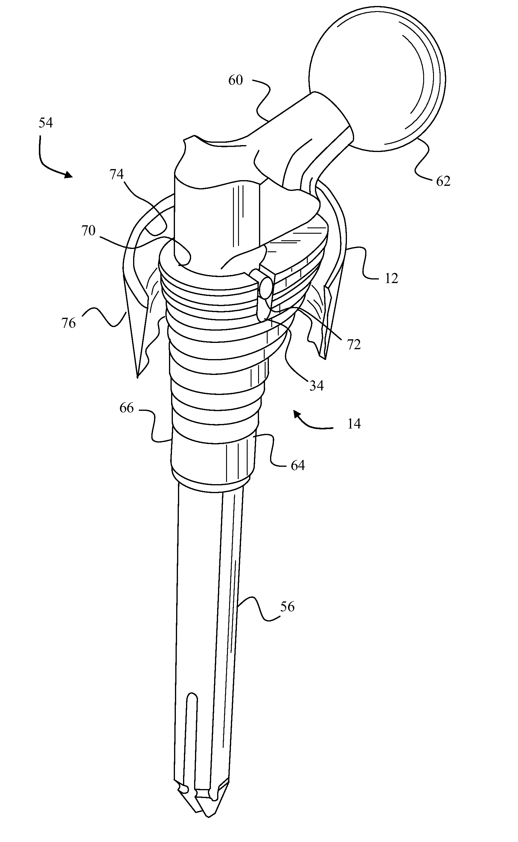
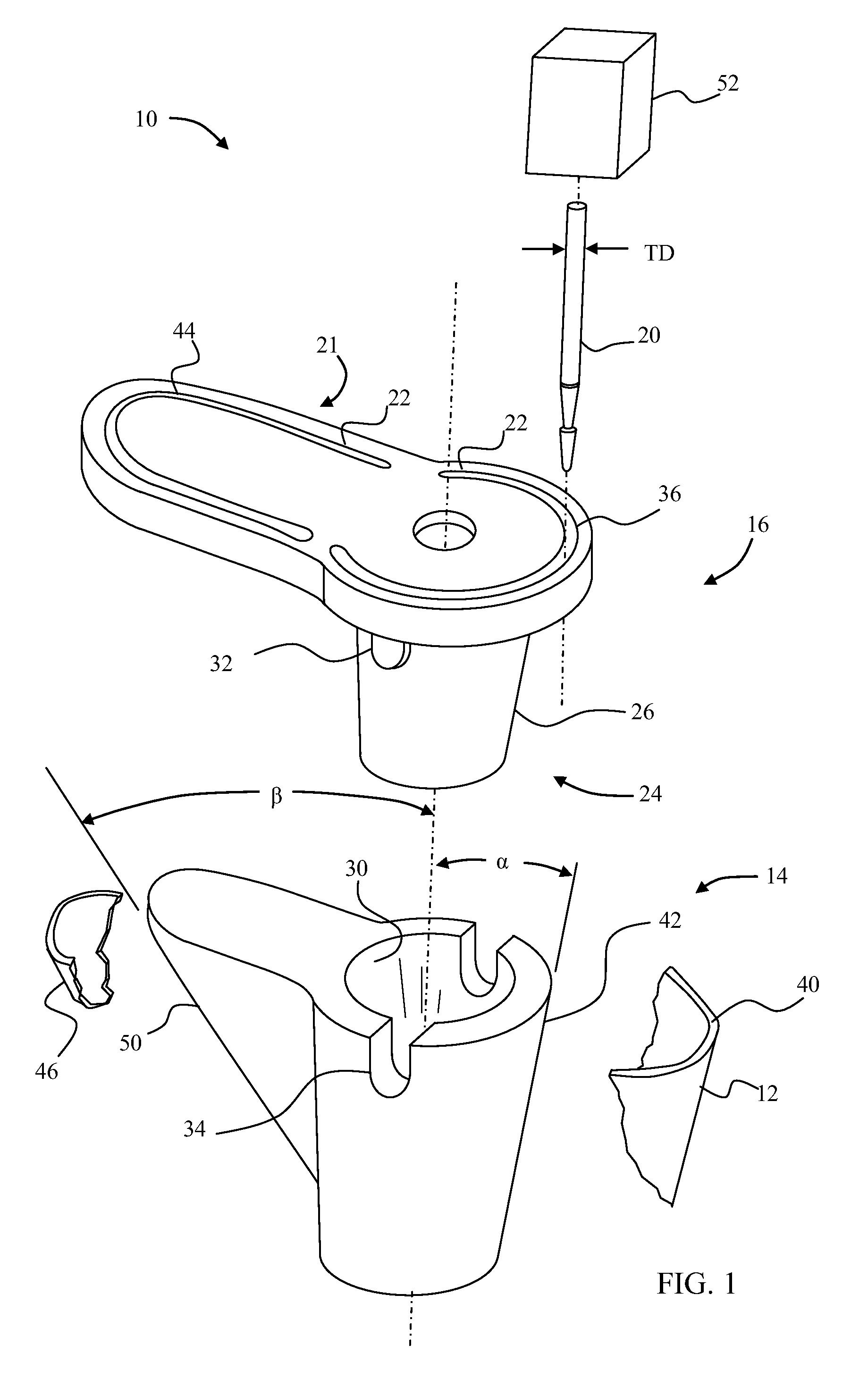
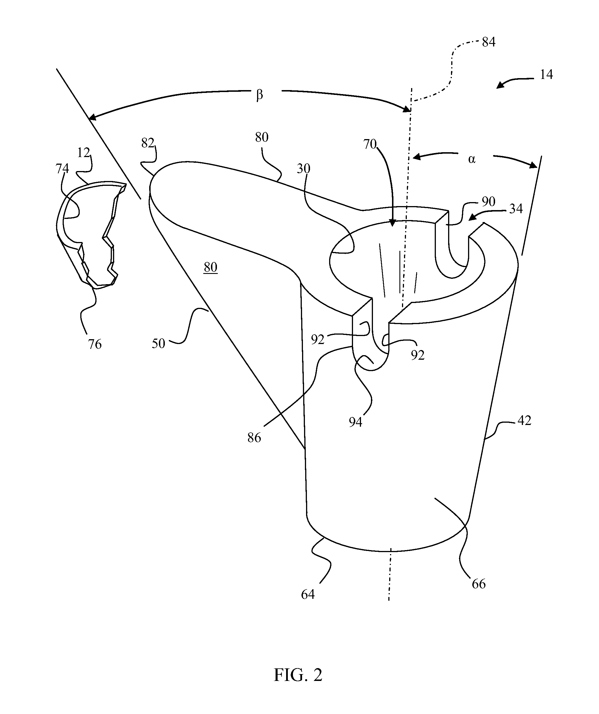
[0032]Embodiments of the present invention and the advantages thereof are best understood by referring to the following descriptions and drawings, wherein like numerals are used for like and corresponding parts of the drawings. According to the present invention and referring now to FIG. 1, a kit 10 is shown. The kit 10 is utilized for removal of bone 12 adjacent to an implanted prosthesis 14. The kit 10 includes a guide 16 for cooperation with the prosthesis 14 and a tool 20. The tool 20 is constrainable by the guide 16 for removal of the bone 12. The guide 16 may include a first portion 22 of the guide 16, which is co-operable with the tool 20. The guide 16 may further include a second portion 24, which is co-operable with the prosthesis 14.

[0033]While it should be appreciated with the first portion, 22 of the guide 16 may have any shape suitable to provide for the guiding of the tool; for example, the first portion 22 may be in the form of a channel. The tool 20 may be guided wit...


PUM


Abstract

A kit (10) for removal of bone (12) adjacent to an implanted prosthesis (14), said kit (10) comprising: a guide (16) for cooperation with the prosthesis (14); and a tool (20) constrainable by said guide (16) for removal of the bone (12).

Description

[0001]This application is a divisional of co-pending application Ser. No. 10 / 176,934, filed Jun. 21, 2002, the disclosure of which is herein totally incorporated by reference in its entirety.CROSS-REFERENCE TO RELATED APPLICATIONS[0002]Cross-reference is made to the following applications: DEP 623 entitled “PROSTHESIS CAVITY CUTTING GUIDE, CUTTING TOOL AND METHOD” and DEP 704 entitled “PROSTHESIS CUTTING GUIDE, CUTTING TOOL AND METHOD” filed concurrently herewith which are incorporated herein by reference.TECHNICAL FIELD OF THE INVENTION[0003]The present invention relates generally to the field of orthopaedics, and more particularly, to an implant for use in arthroplasty.BACKGROUND OF THE INVENTION[0004]Joint replacement surgery is quite common and it enables many individuals to function properly when they otherwise would not be possible to do so. Such patients of joint replacement surgery typically suffer from osteoarthritis or rheumatoid arthritis. Artificial joints usually compri...

Claims


Application Information

Patent Timeline
Patent Type & Authority Applications(United States)
IPC IPC(8): A61B17/56A61B17/17
CPCA61B17/175A61B17/17
Inventor VENDRELY, TIMWILLISON, M. KATHLEENBARNES, LOWRY
Owner DEPUY SYNTHES PROD INC
Why Eureka
Try Eureka