Verifying operation of a meter

a technology of meter and operation method, applied in the direction of measuring device, material analysis by electric/magnetic means, instruments, etc., can solve the problems of meter itself damage, erroneous readings can arise not, and actions taken (e.g. insulin administration) could be detrimental to the user's health

Active Publication Date: 2020-03-31
INSIDE BIOMETRICS
View PDF10 Cites 0 Cited by
  • Summary
  • Abstract
  • Description
  • Claims
  • Application Information

AI Technical Summary

Benefits of technology

[0013]Advantageously, by using a reference transient indicative of a response generated using a non-control (reference) test fluid, and by applying an algorithm designed for use in estimating a concentration of an analyte in a sample of the reference test fluid, the contemplated embodiments allow a user to carry out an integrity check of the algorithm used for measuring concentrations of analytes in test fluids. The described embodiments therefore allow for a more complete system check of the meter as a whole, by testing the part of the system responsible for the blood-analyte measurement (or more generally the test fluid—analyte measurement). The described embodiments provide a further system check for ensuring proper functioning and performance of the meter, and better safeguards the safety of users.

Problems solved by technology

If the reading is erroneous and the user acts upon the erroneous reading, any action taken (e.g. the administration of insulin) could be detrimental to the user's health.
Erroneous readings can arise not only if the test strip is damaged (which could for example affect the flow of the fluid sample across the measurement chamber), but also if the meter itself is damaged.
However, unless a relatively simple measurement / algorithm is used with the control solution (e.g. a single current reading at a fixed time, and a slope and intercept to convert the current value to an analyte reading), control solutions generally do not allow for verification of the integrity of the meter hardware and software responsible for carrying out an analyte measurement when a non-control solution is being tested.
Whilst this could be addressed by developing control solutions that mimic the behaviour of blood (or whatever non-control solution is being tested), such development could not be arrived at without significant time and expense given that blood is a complex matrix sample containing many constituents not present in simple control solutions (such as blood cells).

Method used


Image

  • Verifying operation of a meter
  • Verifying operation of a meter
  • Verifying operation of a meter

Examples


Embodiment Construction

[0033]The present disclosure seeks to provide an improved method of verifying operation of a meter. Whilst various embodiments are described below, the contemplated embodiments are not limited to these embodiments, and variations of these embodiments may well fall within the scope of the appended claims.

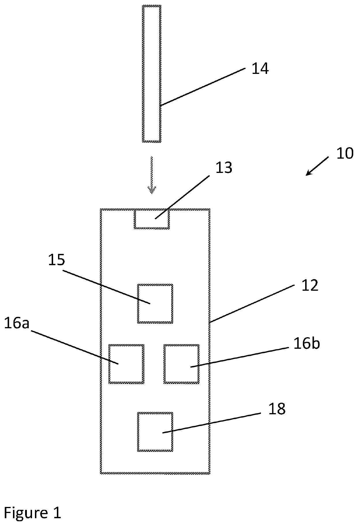
[0034]FIG. 1 shows a strip-meter system 10 according to an embodiment. System 10 comprises a meter 12 for reading an electrochemical test strip 14. Electrochemical test strip 14 comprises one or more working electrode (not shown) and a counter / reference electrode, each of the working electrodes having a reagent coated thereon for reacting with a fluid sample to be applied to electrochemical test strip 14. The counter / reference electrode may also have a reagent coated thereon. Meter 12 comprises receiving means 13 for receiving test strip 14 and applying a potential difference between the working electrode(s) and the counter / reference electrode.

[0035]Meter 12 further comprises process...


PUM

PropertyMeasurementUnit
timeaaaaaaaaaa
timeaaaaaaaaaa
current vs time responseaaaaaaaaaa

Abstract

A method of verifying operation of a meter for reading electrochemical test devices, includes obtaining a reference output signal indicative of a response generated at an electrochemical test device when the electrochemical test device reacts with a reference test fluid; applying with the meter an algorithm to the reference output signal so as to obtain a reference test result, wherein the algorithm is for use in estimating an unknown concentration of an analyte in a sample of the reference test fluid; and determining whether the reference test result is valid so as to verify operation of the meter.

Description

FIELD OF THE INNOVATION[0001]The present disclosure relates to a method of verifying operation of a meter for reading electrochemical test devices. In specific embodiments the test device is an electrochemical test strip as used with bodily fluid meters for determining the concentration of analytes in an individual's bodily fluid sample.BACKGROUND[0002]In the field of diagnostic and monitoring devices as used in the medical device industry, especially those used for analysing blood or other bodily fluid samples, it is often required for users to monitor biometrics such as the levels of certain chemicals, substances, or analytes present in their bloodstream. For instance, diabetics in particular must regularly monitor the concentrations of glucose in their blood in order to determine if they are in need of insulin. In order to respond effectively to an individual's needs to monitor blood sugar levels, diagnostic and monitoring devices and kits have been developed over the years to al...

Claims


Application Information

Patent Timeline
Patent Type & Authority Patents(United States)
IPC IPC(8): G01N27/416G01N27/327G01N33/487
CPCG01N27/3274G01N33/48785
Inventor BLYTHE, STEPHENBASKEYFIELD, DAMIAN
Owner INSIDE BIOMETRICS
Why Eureka
Try Eureka