Dental prosthesis and method for the production thereof

a technology for dental prostheses and teeth, applied in dental prostheses, dentistry, medical science, etc., can solve problems such as difficulties in handling, and achieve the effects of low design complexity, improved handling, and convenient creation

Active Publication Date: 2020-04-07
DENTSPLY IMPLANTS MFG
View PDF32 Cites 2 Cited by
  • Summary
  • Abstract
  • Description
  • Claims
  • Application Information

AI Technical Summary

Benefits of technology

[0003]Proceeding from this, it is the object of the invention to refine the dental prosthesis and / or the metal framework so as to allow improved handling and / or facilitated creation of the, in particular intra-oral, welded joints with low design complexity. Both the work involved and the size of the device that is required to implement the welded joint, the device being designed particularly as pincers and comprising, in particular, the aforementioned electrodes, are to be reduced.
[0004]Moreover, a cap is to be provided, which allows simple handling and / or unproblematic creation of the joint with the connecting element. Moreover, the forces and torque acting on the cap, and ultimately on the metal implant, both during creation of the welded joint and throughout the usage duration of the dental prosthesis, are to be reduced.
[0006]The dental prosthesis according to the invention and / or the metal framework thereof are characterized by a simple, and nonetheless functionally adequate, design, wherein the dentist can easily grab the pin designed as an axial extension of the cap using his fingers, and the cap can be placed without difficulty on the associated abutment of the dental implant implanted into the jaw. The dental prosthesis is a prosthetic restoration that is easy to produce and / or has high stability, and that is designed as an implant, bridge or individual tooth restoration. The pin is an integral part of the cap and has a considerably smaller outer diameter than the cap has at the region thereof facing away from the dental implant. Positioning and fixation of the connecting element close to the axis are thus achieved, whereby reduction of the lever action on the dental implant and / or of the acting forces or torque is advantageously achieved. Due to the reduced diameter of the pin, the device that comprises the welding electrodes, and preferably is designed as pincers, can be designed for a considerably reduced electrode distance, and can have have an accordingly smaller size and / or lower weight, whereby handling is facilitated. The inside space of the cap is designed to be closed at the end thereof facing away from the dental implant, in particular by way of a ceiling, wherein the ceiling and the pin connected thereto, preferably integral therewith, are integral parts of the cap. Preferably, the cap has, or the caps have, conical inner surfaces, corresponding to the conical outer surfaces of the abutments. The inner geometry of the cap comprising the pin is adapted to the geometry of the abutment of the respective implant system. The dental prosthesis and / or the metal framework can thus be used in a simple manner by designing the inner geometry of the cap to correspond to the outer geometry of the abutments of different implant systems. The cap is, or the caps are, prefabricated and / or standard components to which the connecting element, which preferably is designed as a wire or bar made of metal, is welded inside the patient's mouth. The dentist thus produces a stable metal framework directly in the oral cavity of a patient, which is preferably potted into a prepared prosthesis, in particular in the shape of a shell, in a dental laboratory. Within the scope of the invention, the material of the prosthesis is preferably cured after insertion of the prosthesis into the oral cavity, wherein the caps that are connected to each other according to the invention are, and / or have been, placed onto the respective associated abutments. Preparation of a dental cast so as to capture the position and orientation of the dental implants or the abutments thereof, and subsequent production, in particular by way of casting, of the caps of the metal framework in the dental laboratory are dispensed with. Advantageously, considerably higher precision is achieved.

Problems solved by technology

As a result of the relatively large distance between the outer surface of the connecting element and the aforementioned opposing outer surface of the cap, the electrodes and / or the aforementioned pincers have an accordingly large size, whereby handling poses difficulties, considering the space constraints in the oral cavity.

Method used


Image

  • Dental prosthesis and method for the production thereof
  • Dental prosthesis and method for the production thereof
  • Dental prosthesis and method for the production thereof

Examples


Embodiment Construction

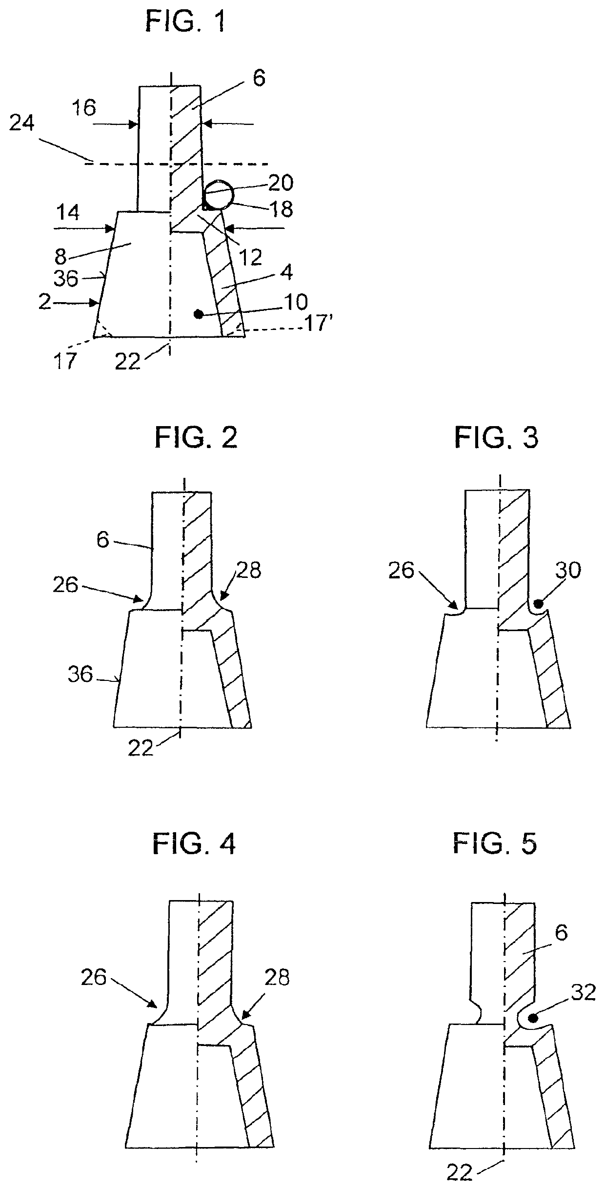
[0016]According to FIG. 1, the cap 2 comprises a conical jacket 4 and a pin 6 as an axial extension, the pin being disposed in the region of the tip 8 of the conical jacket 4. The cap 2 has a cavity 10 on the inside in such a way that the cap can be placed in the known manner onto an abutment of a dental implant, which is not shown in further detail here, and can be joined to the abutment. In the region of the tip 8, the cap 2 has a roof 12, by way of which the pin 6 is connected to the cap 2, preferably in one piece. In this embodiment, the pin 6 essentially adjoins the tip region of the jacket 4, or of the cap 2, at a right angle. This embodiment is easy to produce.

[0017]In the region of the tip 8, the cap 2, or the jacket 4 thereof, has a diameter 14 that is larger, by a predefined factor, than the diameter 16 of the pin 6. The cap 2 designed integrally together with the pin 6 is made of metal, and more particularly titanium or a titanium alloy. At the other end located opposite ...


PUM


Abstract

A dental prosthesis, includes a metal framework having at least one cap, which can be joined to an abutment of a dental implant. The metal framework includes a connecting element which can be, or is, joined to the cap in the oral cavity of a patient, in particular by way of welding, soldering or gluing, wherein the cap has a tip and, on the inside, a cavity into which the abutment can be inserted through an opening located opposite the tip. It is the object to refine the dental prosthesis and / or the metal framework so as to allow improved handling and / or facilitated creation of the, in particular intra-oral, preferably welded, joint with low design complexity. This object is attained by providing a pin arranged as an axial extension in the region of the tip of the cap and the connecting element is joined to the pin.

Description

BACKGROUND OF THE INVENTION[0001]The invention relates to a dental prosthesis, comprising a metal framework and to a method for the production thereof.[0002]Such a dental prosthesis and the method for producing the dental prosthesis are described in issue 3_2005 of the magazine “implants” in the report “intra-oral welding of temporary implant abutments with a pre-fabricated titanium bar.” The dental prosthesis comprises a metal framework, which is made in particular of titanium, or a titanium alloy, and comprises one or more caps and a connecting element in the form of a wire or a bar. The caps and the connecting element are joined by way of electric welding, wherein the connecting regions are located at the outer surfaces of the caps, which in particular face the tongue. The cap includes, or the caps include, a cavity on the inside, and are designed to be open at the end facing away from an implant. After dental implants have been implanted into a jaw, the caps are placed onto abut...

Claims


Application Information

Patent Timeline
Patent Type & Authority Patents(United States)
IPC IPC(8): A61C13/20A61C8/00
CPCA61C8/0048A61C8/0078A61C13/20A61C8/005
Inventor DEGIDI, MARCO
Owner DENTSPLY IMPLANTS MFG
Why Eureka
Try Eureka