
Rim drilling and milling machine

a drilling and milling machine technology, applied in the direction of manufacturing tools, transportation and packaging, other manufacturing equipment/tools, etc., can solve the problems of poor clamping stability of conventional drilling and milling machines, and achieve excellent clamping stability

Active Publication Date: 2020-04-07
TOP ONE MACHINERY CO LTD
View PDF21 Cites 22 Cited by
  • Summary
  • Abstract
  • Description
  • Claims
  • Application Information

AI Technical Summary

Benefits of technology

The invention is a drilling and milling machine for a wheel rim that has four clamping seats. These seats can securely hold the wheel rim in place at four specific points, ensuring stability during the process. This machine allows for efficient and accurate drilling and milling of wheels.

Problems solved by technology

However, the conventional drilling and milling machine has a poor clamping stability, because the wheel rim 80 is only clamped by two dampers 95 which are arranged at a spaced interval along a longitudinal line of the table 942 to clamp diametrically opposite sides of the wheel rim 80.

Method used


Image

  • Rim drilling and milling machine
  • Rim drilling and milling machine
  • Rim drilling and milling machine

Examples


Embodiment Construction

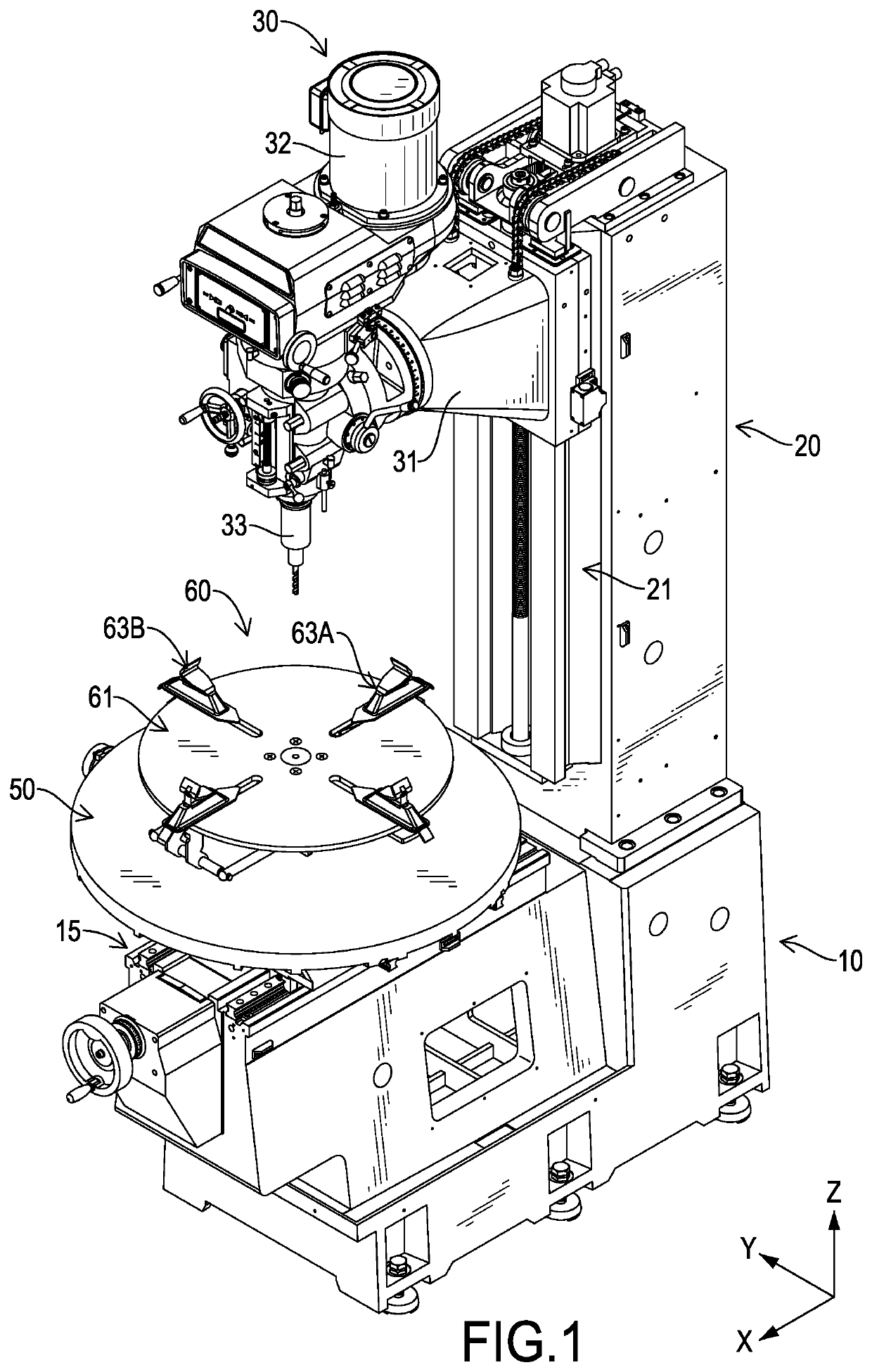
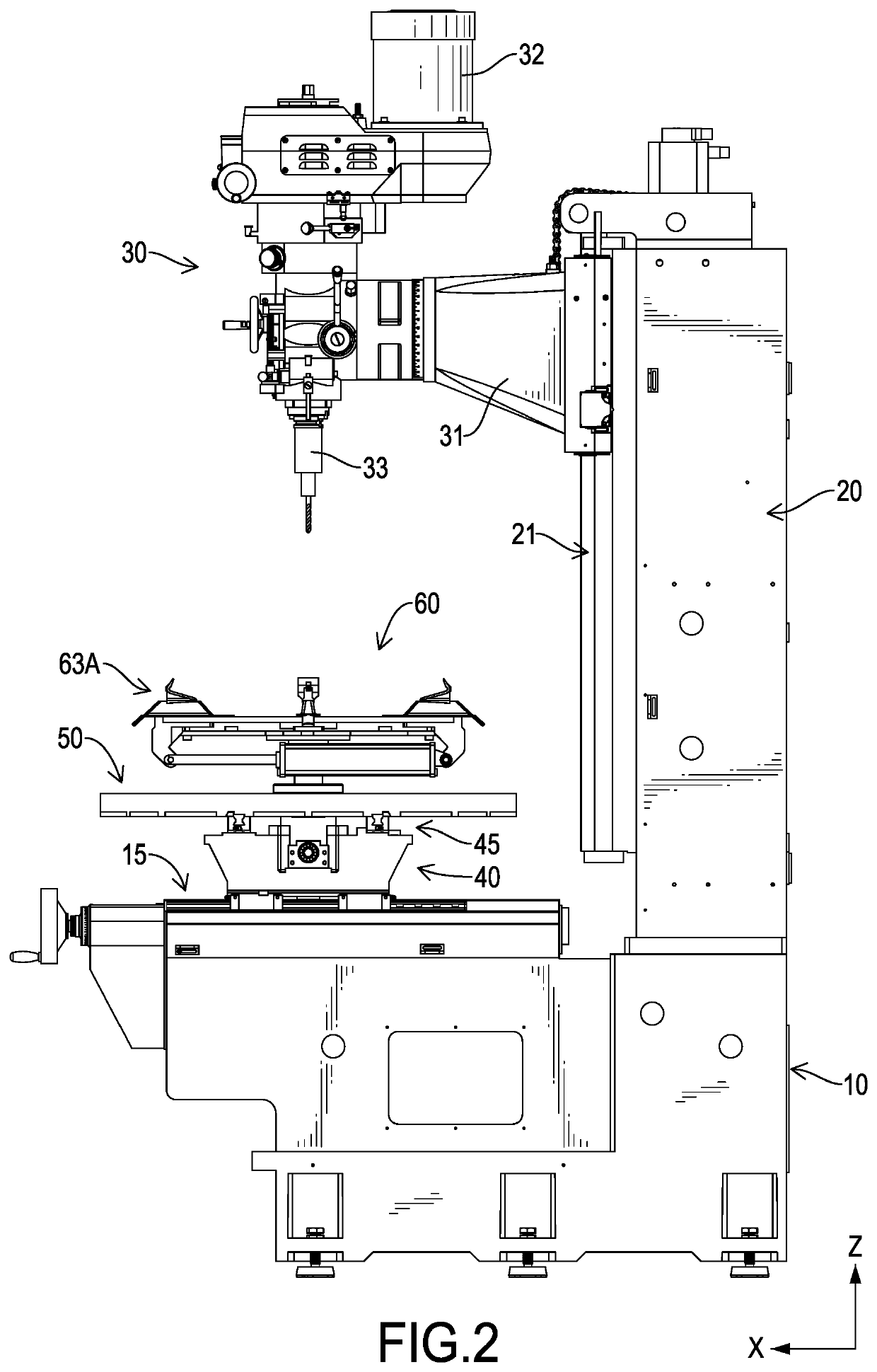
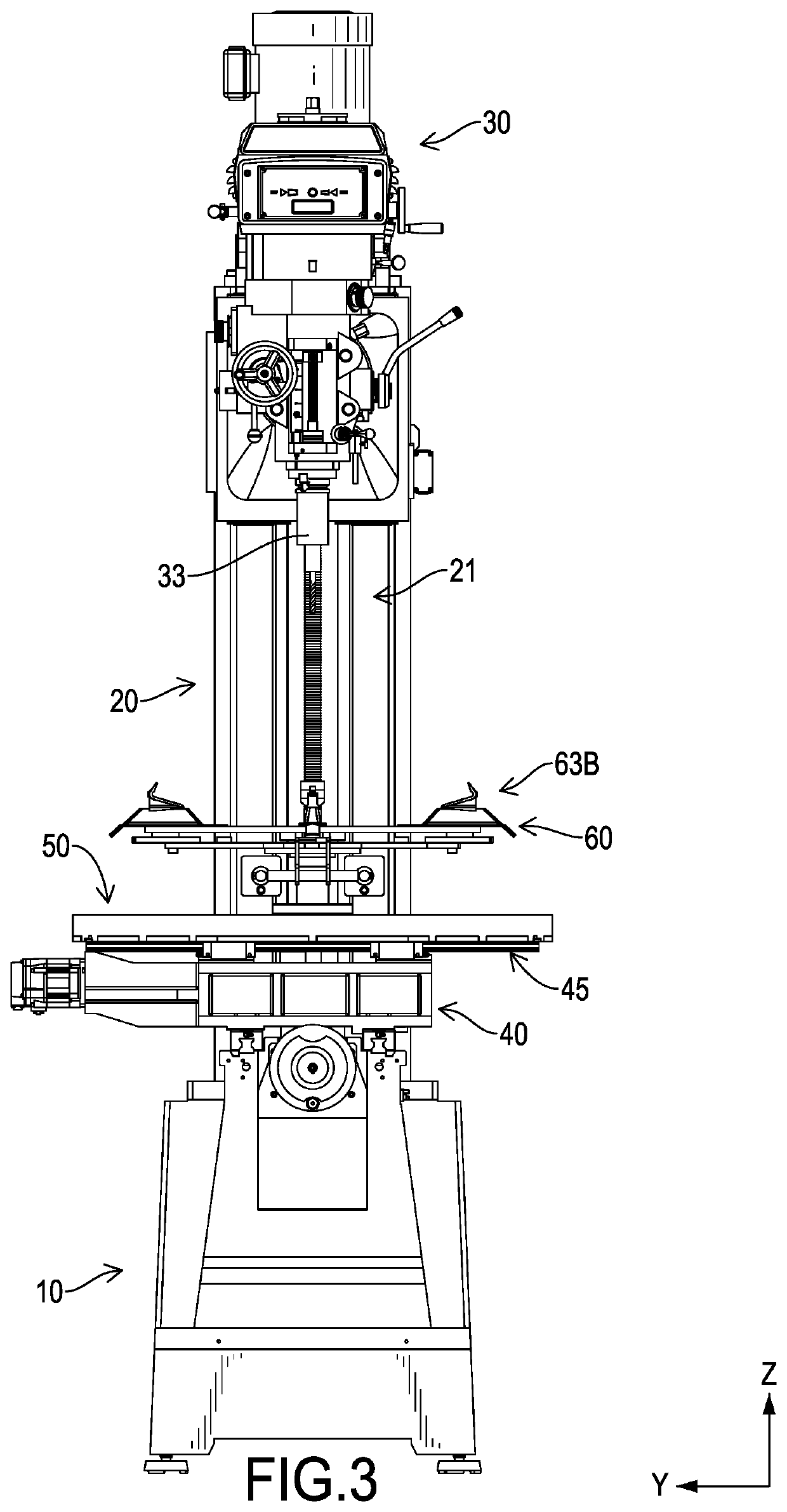
[0019]With reference to FIGS. 1 to 3, a rim drilling and milling machine in accordance with the present invention has a first axis X, a second axis Y, a third axis Z, a base 10, a column 20, a turret 30, a saddle 40, a table 50, and a fixture unit 60. The first axis X, the second axis Y, and the third axis Z are perpendicular to one another, and the third axis Z is vertical and perpendicular to the horizontal plane.

[0020]The column 20 is fixed on the base 10, protrudes upward from the top of the base 10, and has a vertical rail unit 21 extending along the third axis Z. The turret 30 is perpendicularly and slidably connected with the vertical rail unit 21 and has a sliding seat 31, a cutter driving unit 32, and a cutter 33. The sliding seat 31 is perpendicularly and slidably connected with the vertical rail unit 21. The cutter driving unit 32 is applied to drive the cutter 33 for processing a wheel rim.

[0021]With reference to FIGS. 5 and 6, the saddle 40 is horizontally and linearly ...


PUM

PropertyMeasurementUnit
Timeaaaaaaaaaa
Currentaaaaaaaaaa
Digital informationaaaaaaaaaa

Abstract

A rim drilling and milling machine has a base (10), a column (20), a turret (30), a saddle (40), a table (50), and a fixture unit (60). The fixture unit (60) has a foundation (61) and four clamping seats defined as two first clamping seats (63A) and two second clamping seats (63B). The first clamping seats (63A) are slidably mounted on the foundation (61) along a first radial direction, and are disposed at positions diametrically opposite in the first radial direction. The second clamping seats (63B) are slidably mounted on the foundation (61) along a second radial direction perpendicular to the first radial direction, and are disposed at positions diametrically opposite in the second radial direction. The four clamping seats can clamp at four equiangular points of a wheel rim.

Description

BACKGROUND OF THE INVENTION1. Field of the Invention[0001]The present invention relates to a rim drilling and milling machine, and more particularly to a rim drilling and milling machine that has an excellent clamping stability by having four clamping seats to clamp at four equiangular points of a wheel rim.2. Description of Related Art[0002]With reference to FIG. 11, a conventional drilling and milling machine substantially has a base 91, a column 92, a turret 93, and a saddle unit 94. The base 91 has a first rail unit 911. The column 92 is fixed on the base 91, protrudes upward from the base 91, and has a vertical rail unit 921. The turret 93 is perpendicularly and slidably connected with the vertical rail unit 921. The saddle unit 94 has a saddle 941 and a table 942. The saddle 941 is slidably connected with the first rail unit 911. The table 942 is connected with the saddle 941, and is horizontally and linearly slidable relative to the saddle 941 along a direction perpendicular ...

Claims


Application Information

Patent Timeline
IPC IPC(8): B23C3/00B23P23/02B23Q1/44B23Q3/06B23Q1/62B23Q1/48B23B31/16B23C1/12B23B41/00
CPCB23C3/00B23Q1/44B23B31/16287B23Q3/062B23C1/12B23B41/00B23Q1/4852B23Q1/621B23P23/02Y10T409/309016B23B2215/08B60B2320/50Y10T409/307672B60B2310/232B23Q2703/10Y10T409/3056Y10T408/93Y10T279/1291B23C2215/085B23B2231/30Y10T279/1953Y10T29/5105B23B31/16B23Q1/5425
Inventor LIU, TSUI-O
Owner TOP ONE MACHINERY CO LTD
Features
  • Generate Ideas
  • Intellectual Property
  • Life Sciences
  • Materials
  • Tech Scout
  • Unparalleled Data Quality
  • Higher Quality Content
  • 60% Fewer Hallucinations
Learn More