Optical connector

a technology of optical connectors and connectors, applied in the field of optical connectors, can solve the problems of optical loss between the lens and affecting the optical transmission performance of the optical conversion module, and forming gaps, etc., and achieve the effect of excellent optical transmission and high accuracy

Active Publication Date: 2020-04-14
YAZAKI CORP
View PDF7 Cites 0 Cited by
  • Summary
  • Abstract
  • Description
  • Claims
  • Application Information

AI Technical Summary

Benefits of technology

[0005]One or more embodiments provide an optical connector excellent in optical transmission and capable of positioning and supporting an optical conversion module with high accuracy without looseness with respect to a housing.

Problems solved by technology

According to a related art, in an optical connector having the structure described above, when the optical conversion module (FOT) is loosened relative to the housing, positional displacement occurs between the lens and the optical conversion module due to the looseness, and optical loss occurs between the lens and the optical conversion module.
Further, if the support of the optical conversion module with respect to the housing is weak, the optical conversion module may be displaced or inclined with respect to the housing due to a force applied at the time of adjusting and aligning positions of a plurality of lead frames extending from the optical conversion module.
Further, a gap is formed, due to the protruding portion, between the optical conversion module fitted into the accommodation portion and the upper wall portion of the accommodation portion.

Method used


Image

  • Optical connector
  • Optical connector
  • Optical connector

Examples


Embodiment Construction

[0035]Hereinafter, an embodiment according to the present invention will be described with reference to the drawings.

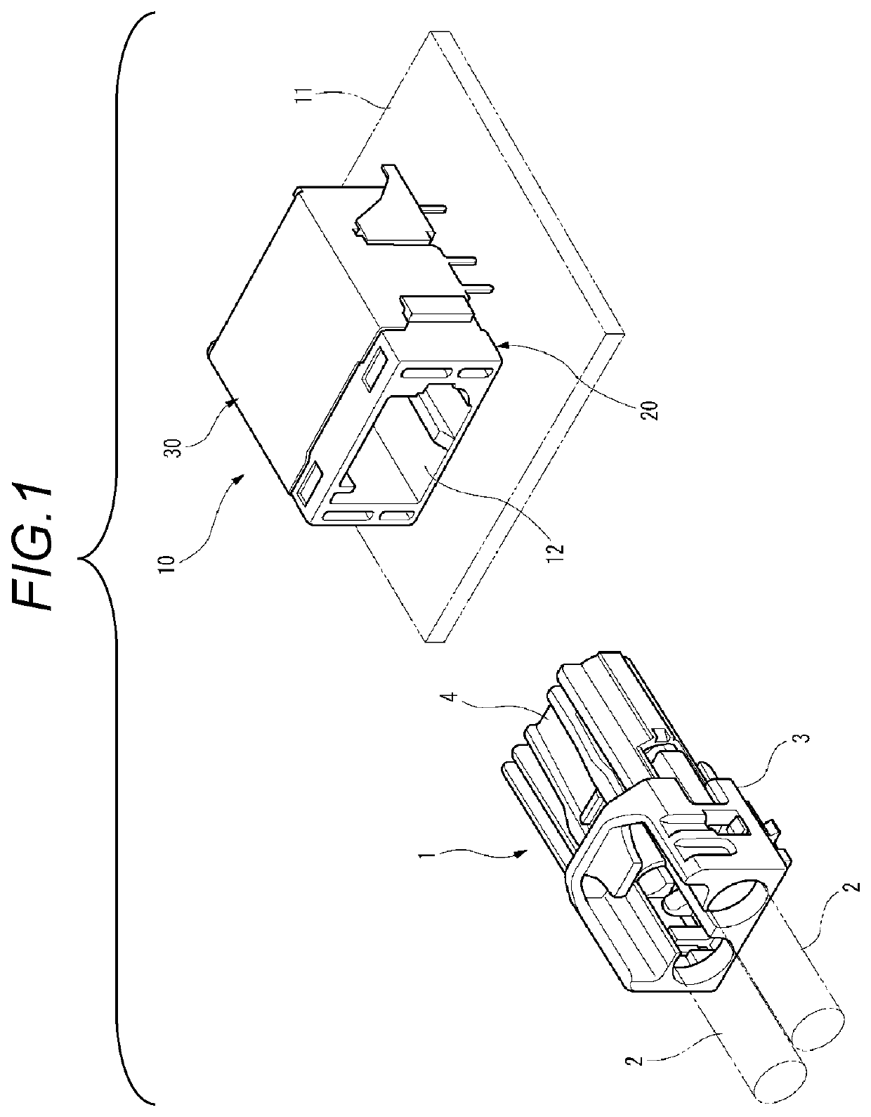
[0036]FIG. 1 is a perspective view of an optical connector according to the present embodiment and a mating side optical connector.

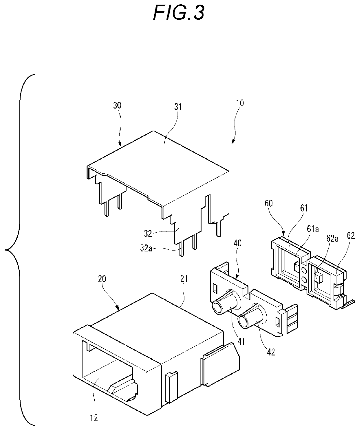
[0037]As shown in FIG. 1, an optical connector 10 according to the present embodiment is a receptacle optical connector to which a mating side optical connector 1 as a plug connector is fitted. The optical connector 10 is mounted on a circuit board 11, and the mating side optical connector 1 is fitted into a fitting recessed portion 12 in the optical connector 10.

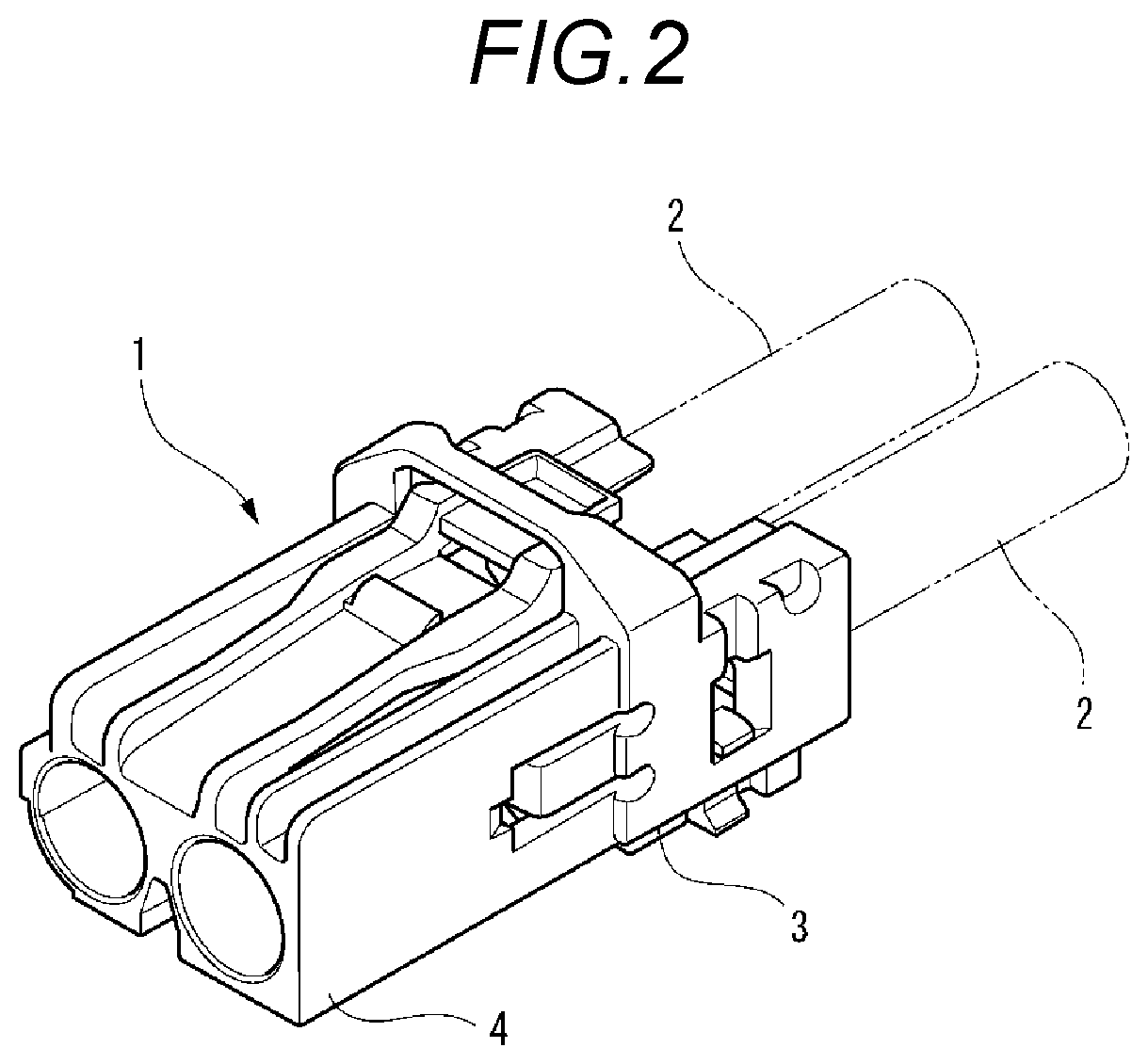
[0038]FIG. 2 is a perspective view of the mating side optical connector.

[0039]As shown in FIG. 2, the mating side optical connector 1 includes a housing 3 connected to an end portion of an optical fiber 2. A front end of the housing 3 is a fitting portion 4, and the fitting portion 4 is fitted into the fitting recessed portion 12 of the optical connector 10. Accordingly, the optic...


PUM

PropertyMeasurementUnit
widthaaaaaaaaaa
heightaaaaaaaaaa
optical lossaaaaaaaaaa

Abstract

An optical connector includes a lens body including a lens portion, an optical conversion module, and a housing including an accommodation portion having a recessed portion, the optical conversion module combined with the lens body being fitted and assembled into the accommodation portion. The optical conversion module includes a light element disposed at a position facing the lens portion when combining the optical conversion module with the lens body. The housing includes a longitudinal support mechanism. The longitudinal support mechanism includes a reference surface and a pressing rib.

Description

CROSS REFERENCE TO RELATED APPLICATIONS[0001]This application claims priority from Japanese Patent Application No. 2018-073414 filed on Apr. 5, 2018, the entire contents of which are incorporated herein by reference.BACKGROUND OF THE INVENTIONField of the Invention[0002]The present invention relates to an optical connector.Description of Related Art[0003]There has been known an optical connector used in the field of optical communication that includes a housing, a shield case, a transmission / reception integrated lens, a light emitting side fiber optic transceiver (FOT), and a light receiving side FOT (for example, see Patent Document 1: JP-A-2014-222256).[Patent Document 1] JP-A-2014-222256[0004]According to a related art, in an optical connector having the structure described above, when the optical conversion module (FOT) is loosened relative to the housing, positional displacement occurs between the lens and the optical conversion module due to the looseness, and optical loss occ...

Claims


Application Information

Patent Timeline
Patent Type & Authority Patents(United States)
IPC IPC(8): G02B6/36G02B6/42
CPCG02B6/4245G02B6/4246G02B6/4262G02B6/4206G02B6/4292G02B6/4204G02B6/4228G02B6/426G02B6/4244G02B6/4256
Inventor HIKOSAKA, TOMOHIRO
Owner YAZAKI CORP
Why Eureka
Try Eureka