Optical component, optical amplification module, and optical transmission system

a technology of optical amplifier and optical component, applied in the direction of optical components, optical transmission with multiple stages, instruments, etc., can solve the problems of complex control over the loss slope, the s/n ratio of signal light amplified in the optical amplifier is varied and degraded, and the loss level of the signal wavelength band is variable in the signal wavelength band, etc., to achieve better optical amplifier, improve the effect of accuracy and high accuracy

Inactive Publication Date: 2006-04-11
SUMITOMO ELECTRIC IND LTD
View PDF6 Cites 1 Cited by
  • Summary
  • Abstract
  • Description
  • Claims
  • Application Information

AI Technical Summary

Benefits of technology

[0009]In order to overcome this problem, Document 3 (the brochure of International Publication WO01 / 05005) suggests an optical filter suitable for the gain equalizers and others in the optical amplifiers, simple in structure, and easy in control over the loss slope. The Inventors conducted various experiments using the optical filter described in above Document 3. During the experiments the Inventors found that in some cases perfect compensation for the gain slope was not possible by only the optical filter described in above Document 3.
[0022]An optical transmission system according to the present invention comprises the optical component of the structure as described above (the optical component according to the present invention). Since the optical transmission system of this configuration can achieve the action of the above optical component, it can function as a better optical transmission system. The optical transmission system according to the present invention preferably further comprises a variable loss slope compensator.

Problems solved by technology

However, the change of the loss slope of the optical filter according to the optical power of input signal results in variation in the loss level in the signal wavelength band.
This means that S / N ratios of the signal light amplified in the optical amplifier vary and degrade.
This optical filter also requires simultaneous control over many heaters (six heaters) for the adjustment of the loss slope, so that the control is complicated over the loss slope.

Method used


Image

  • Optical component, optical amplification module, and optical transmission system
  • Optical component, optical amplification module, and optical transmission system
  • Optical component, optical amplification module, and optical transmission system

Examples


first embodiment

of Optical Amplification Module

[0054]The optical filter 1 of the first embodiment, the optical filter 2 of the second embodiment, and the optical filter 3 of the third embodiment as described above can be applied to optical amplification modules constituting optical transmission systems. FIG. 9 is a diagram showing the structure of an optical amplification module (the first embodiment of the optical amplification module according to the present invention) to which one of these optical filters 1–3 can be applied.

[0055]The optical amplification module 100 according to the first embodiment is arranged in series with a variable gain slope compensator 109 on a transmission line. The optical amplification module 100 includes the following components arranged in the order named from light input end 110 toward light output end 111: isolator 103a, optical coupler 108a, amplification optical fiber 101a, isolator 103b, optical filter 106, optical coupler 108b, amplification optical fiber 101b,...

second embodiment

of Optical Amplification Module

[0059]FIG. 10 is a diagram showing the structure of the optical amplification module according to the second embodiment. One selected from the optical filters 1–3 of the first to third embodiments having the structures as described above is applied to the optical amplification module 200 in the second embodiment. The optical amplification module 200 of the second embodiment is different from the optical amplification module 100 of the first embodiment described above, in that the variable gain slope compensator 109 is disposed between the isolator 103b and the optical coupler 108, the amplification optical fiber 101c is divided into amplification optical fiber 101d and amplification optical fiber 10le, and the optical filter 106 is disposed between amplification optical fiber 101d and amplification optical fiber 101e. The reason why the optical filter 106 is disposed in this way is that there is a need for adapting to increase of insertion loss due to ...

third embodiment

of Optical Amplification Module

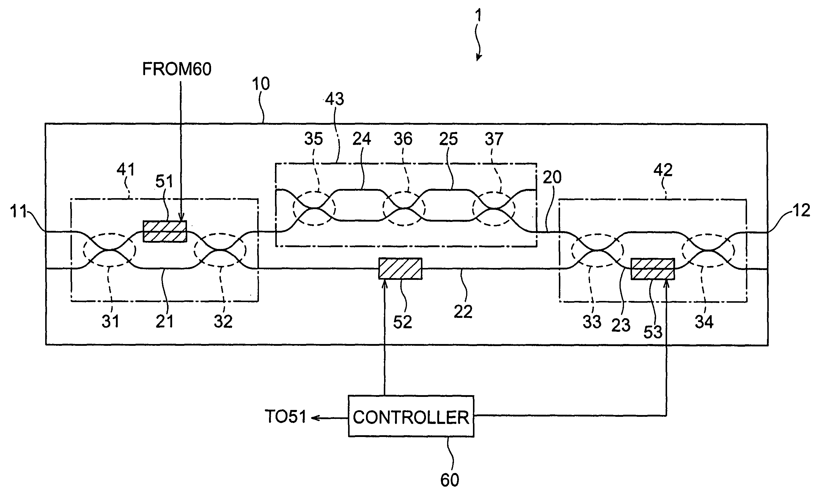
[0060]FIGS. 11A and 11B are diagrams showing configurations of the optical amplification module according to the third embodiment. The optical amplification module of the third embodiment is constructed of a combination of one selected from the optical filters 1–3 of the first to third embodiments having the structures as described above, with an optical fiber amplifier, in which the optical filter 1–3 functions as a tunable gain equalizer.

[0061]FIG. 11A is a diagram showing a configuration of a first design example of the optical amplification module according to the third embodiment. The optical amplification module 300a of the first design example is provided with the following components arranged in the order named from light input end 301 toward light output end 302: demultiplexer 303a, optical fiber amplifier 304a (Amp), optical component 305 functioning as a tunable gain equalizer (which is an optical component according to the present invention...


PUM

PropertyMeasurementUnit
wavelength rangeaaaaaaaaaa
wavelengthaaaaaaaaaa

Abstract

The present invention relates to an optical component and others in structure capable of implementing improved compensation for a gain slope. The optical component is equipped with first and second Mach-Zehnder interferometers. The first Mach-Zehnder interferometer is provided with a first temperature controller for controlling a temperature of at least one of a part of an optical main path and a first optical side path, while the second Mach-Zehnder interferometer 42 is also provided with a second temperature controller for controlling a temperature of at least one of a part of the optical main path and a second optical side path. A filter circuit having a wavelength-dependent insertion loss is disposed between the first and second Mach-Zehnder interferometers, and a controller controls the temperatures of the optical paths by use of the first and second temperature controllers on the basis of the insertion loss of the filter circuit, thereby setting a loss for light of a predetermined wavelength propagating between a light input end and a light output end.

Description

BACKGROUND OF THE INVENTION[0001]1. Field of the Invention[0002]The present invention relates to an optical component mainly suitable for such a devices as gain equalizers for equalizing the gain of amplification of signal light in optical amplifiers, an optical amplification module incorporating the optical component, and an optical transmission system incorporating the optical component.[0003]2. Related Background Art[0004]The optical amplifiers are provided with an optical waveguide doped with a fluorescent substance which can be pumped by pumping light, and a pumping means for supplying the pumping light into the optical waveguide, and are provided in repeaters or the like in optical transmission systems. Particularly, in the case of the optical amplifiers applied to the WDM (Wavelength Division Multiplexing) optical transmission systems for transmitting signal light in which a plurality of signal channels of mutually different wavelengths are multiplexed (multiplexed signal lig...

Claims


Application Information

Patent Timeline
Patent Type & Authority Patents(United States)
IPC IPC(8): H01S3/00G02B6/26G02F1/01G02F1/225
CPCH04B10/2941G02F1/225G02F1/0147H04B2210/003
Inventor HATAYAMA, HITOSHIKAKUI, MOTOKISHITOMI, TATSUHIKOSHIGEMATSU, MASAYUKI
Owner SUMITOMO ELECTRIC IND LTD
Why Eureka
Try Eureka