
Method for estimating resistances of a source contact and a drain contact of a MOS transistor

a technology of mos transistor and source contact, which is applied in the direction of resistance/reactance/impedence, measurement devices, instruments, etc., can solve the problems of additional parasitic resistance and drive current degradation, and achieve the effect of accurate extraction of source contact resistance, simple methodology and alleviation of parasitic resistan

Active Publication Date: 2020-04-21
NAN YA TECH
View PDF5 Cites 0 Cited by
  • Summary
  • Abstract
  • Description
  • Claims
  • Application Information

AI Technical Summary

Benefits of technology

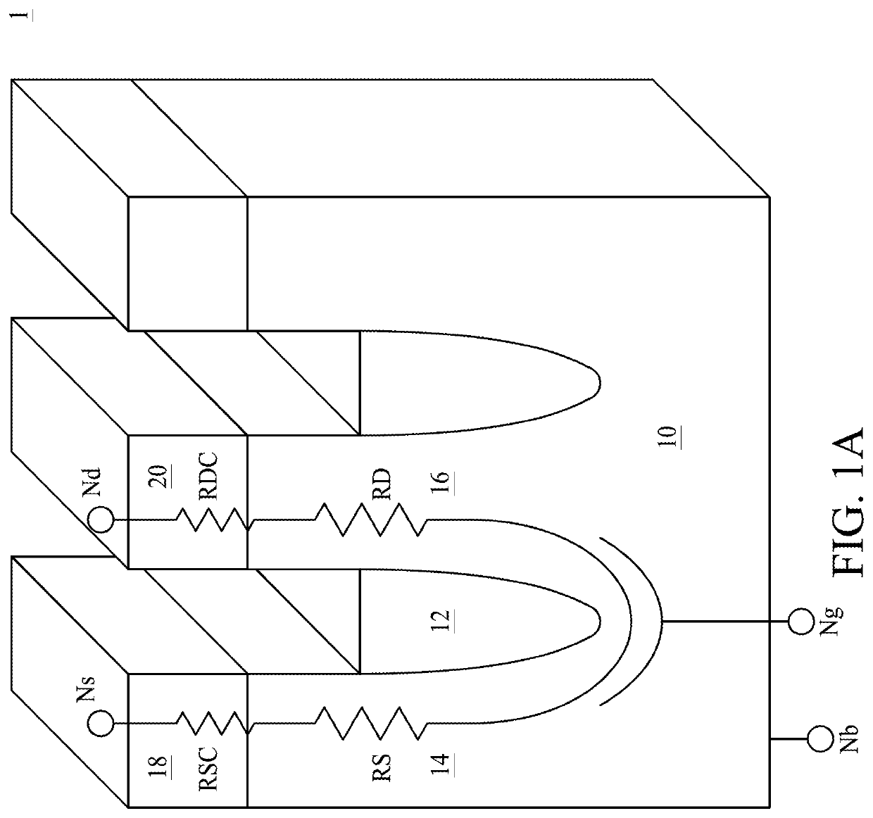
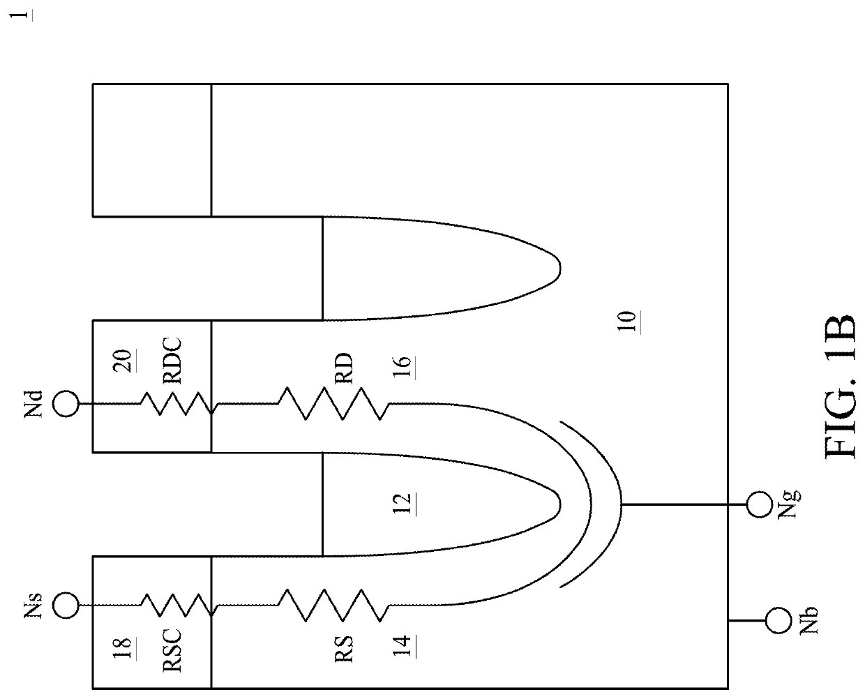
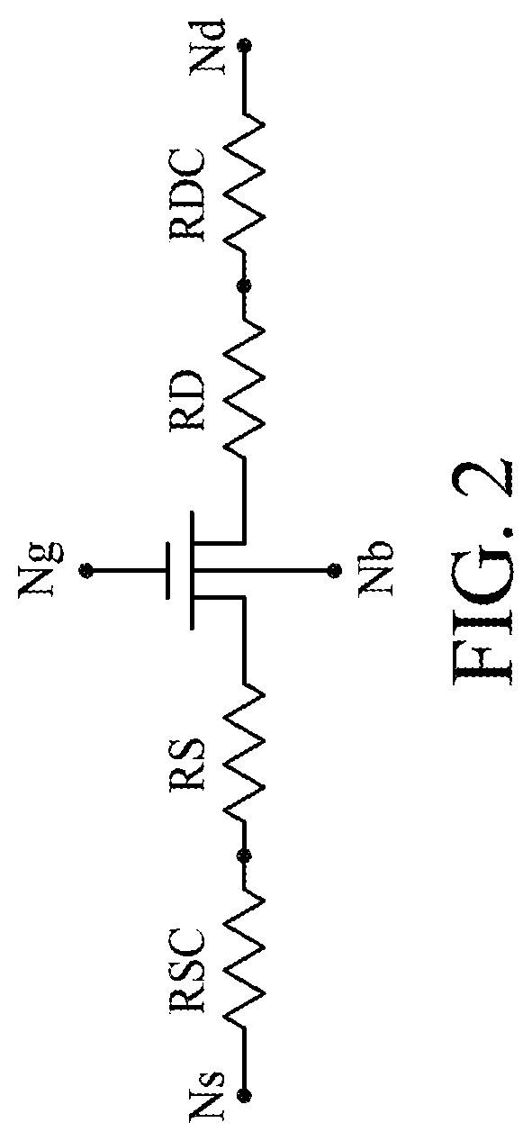
[0016]In some embodiments of the present disclosure, a method for estimating resistances of a source contact and a drain contact of a MOS transistor is provided. The method uses four equations derived from Ohm's law to estimate the resistance of a source contact and the resistance of a drain contact of a MOS transistor. The method is designed to estimate the resistance of a source contact and the resistance of a drain contact of a single MOS transistor, and thus can be applied to various semiconductor devices such as a vertical MOS transistor, a horizontal MOS transistor, and the like. The method is able to accurately extract the resistance of the source contact and the resistance of the drain contact from the overall resistance of the MOS transistor by a simple methodology, and can alleviate the influence of parasitic resistance. Accordingly, the integrated circuit performance can be accurately accessed.

Problems solved by technology

The parasitic source and drain resistances resulting from the source contact and the drain contact may lead to degradation of drive current.
In contrast, conventional methods use a complex measurement technique which connects voltage and ampere meters to the MOS transistor, and may cause additional parasitic resistance.

Method used


Image

  • Method for estimating resistances of a source contact and a drain contact of a MOS transistor
  • Method for estimating resistances of a source contact and a drain contact of a MOS transistor
  • Method for estimating resistances of a source contact and a drain contact of a MOS transistor

Examples


Embodiment Construction

[0026]Embodiments, or examples, of the disclosure illustrated in the drawings are now described using specific language. It shall be understood that no limitation of the scope of the disclosure is hereby intended. Any alteration or modification of the described embodiments, and any further applications of principles described in this document, are to be considered as normally occurring to one of ordinary skill in the art to which the disclosure relates. Reference numerals may be repeated throughout the embodiments, but this does not necessarily mean that feature(s) of one embodiment apply to another embodiment, even if they share the same reference numeral.

[0027]It shall be understood that, although the terms first, second, third, etc. may be used herein to describe various elements, components, regions, layers or sections, these elements, components, regions, layers or sections are not limited by these terms. Rather, these terms are merely used to distinguish one element, component...


PUM

PropertyMeasurementUnit
resistanceaaaaaaaaaa
resistancesaaaaaaaaaa

Abstract

A method for estimating resistances of a source contact and a drain contact of a MOS transistor includes the following steps. A MOS transistor is provided. The MOS transistor includes a substrate, a gate, a source region and a drain region, a source contact electrically connected to the source region, and a drain contact electrically connected to the drain region. A resistance difference between a source contact resistance and a drain contact resistance is obtained. A resistance sum of the source contact resistance and the drain contact resistance is obtained. The source contact resistance and the drain contact resistance are calculated based on the resistance sum of the source contact resistance and the drain contact resistance, and on the resistance difference between the source contact resistance and the drain contact resistance.

Description

PRIORITY CLAIM AND CROSS-REFERENCE[0001]This application claims priority of U.S. provisional application Ser. No. 62 / 595,800, filed on Dec. 7, 2017, which is incorporated herein by reference in its entirety.TECHNICAL FIELD[0002]The present disclosure relates to a method for estimating resistances of a source contact and a drain contact of a MOS transistor, and more particularly, to a method for extracting resistances of a source contact and a drain contact from an overall resistance of the MOS transistor.DISCUSSION OF THE BACKGROUND[0003]Metal oxide semiconductor (MOS) transistors have several sources of electrical resistance connected in series, including a resistance of a source contact, a resistance of a source region, a resistance of a drain region and a resistance of a drain contact. Accurate measurement of the individual resistance values of the source contact, the source region, the drain region and the drain contact is critical for assessing integrated circuit performance.[0...

Claims


Application Information

Patent Timeline
Patent Type & Authority Patents(United States)
IPC IPC(8): G01R31/26G01R27/08
CPCG01R31/2621G01R27/08
Inventor LIN, SHIH-TINGFAN, KUNG-MINGXSIAO, HUNG-HSIANG
Owner NAN YA TECH
Learn More