
Corrective lens apparatus and method

a technology of corrective lenses and lenses, applied in the field of corrective lenses, can solve the problems of poor adaptability, thick lenses, and inadequate nature of corrective lenses, especially in combination with safety or protective eyewear, and achieve the effect of protecting from fogging and high glar

Active Publication Date: 2020-04-21
QUINTANA ALEJANDRO A GOEBEL
View PDF6 Cites 2 Cited by
  • Summary
  • Abstract
  • Description
  • Claims
  • Application Information

AI Technical Summary

Benefits of technology

The invention relates to a new type of lens design for eyewear, such as sunglasses and sport goggles. The lens has a unique structure with raised portions that can be used for corrective lenses or polarized eyewear. The design also has an intersection between the raised portions and the lens that is curved or angled to minimize potential distortion and light refraction issues. The lens is made using a removable tooling engagement member that allows for customization to users. Overall, the invention provides a lens with improved performance and customization options for both corrective and polarized eyewear.

Problems solved by technology

As a general rule, such eyesight problems are a result of the physical characteristics of the eye of the person requiring corrective lenses.
In some instances the nature of construction of corrective lenses, especially in combination with safety or protective eyewear, has been less than adequate.
For example, users of corrective lenses who suffer from severe farsightedness require very thick lenses to correct their vision, which are not well adapted for use in combination with a shield type eyewear such a goggles.
Further, such thick lenses have perimeters which limit the engagement to eyeglass frames.
Further, those with nearsightedness or farsightedness or who suffer from other vision acuity problems also have problems trying to wear protective goggles such as military members who wear goggles, or others who wear sport goggles for activities such as skiing or motorcycling.
The problem of corrective lenses is also an issue when combined with workers who must wear safety goggles.
Such has led to poor vision from fogging, glare from the interaction of spaced refraction surfaces, shadow images caused by the spaced lenses, and other issues caused by the interaction between the eyeglass lenses spaced from the goggle lens or lenses.
Additionally, refraction of light through the sidewall of the projecting portions and adjacent their intersection with the front panoramic lens, as taught by the Quintana reference, may generate refractive qualities such as colorized light, which has been found to be distracting to users.
Additionally, when employed for goggles which form a sealed cavity in front of the face of the user, the dissimilar thicknesses of the panoramic lens or shield areas thereof with projecting portions, can have thermal issues during formation due to the retention of heat in the thicker areas.
Additionally, no prior art teaches a manner in which smaller projections on a curved panoramic shield can be ground to required characteristics to provide vision correction to a wearer.
Still further, such a device and method should provide projections on the frontal panoramic lens which are machinable to corrective lenses using conventional lens grinding machinery, in spite of the large and highly curved panoramic lens surrounding the projecting portions.
Various limitations of the related prior art will become apparent to those skilled in the art upon a reading and understanding of the specification below and the accompanying drawings.

Method used


Image

  • Corrective lens apparatus and method
  • Corrective lens apparatus and method
  • Corrective lens apparatus and method

Examples


Embodiment Construction

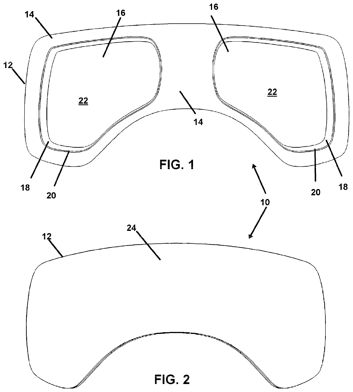
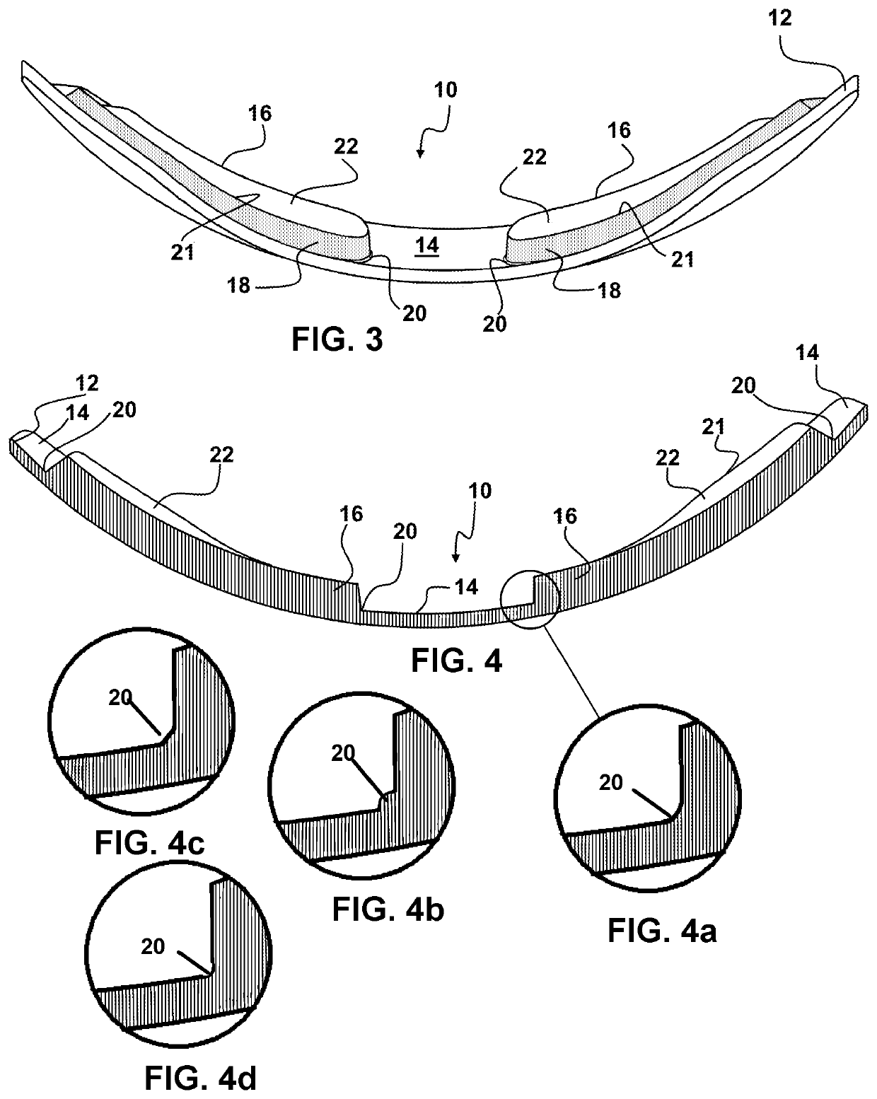
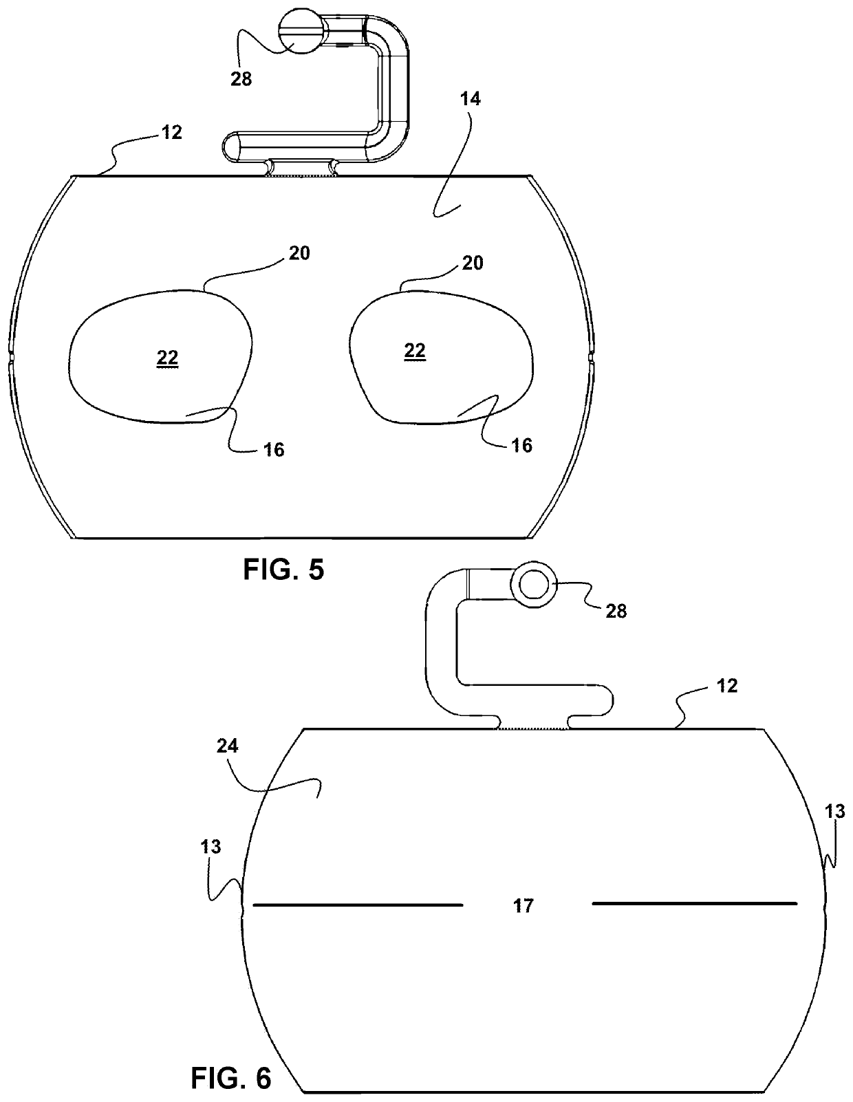
[0056]Now referring to drawings of FIGS. 1-19, where similar structures are described with like numerals there is seen in FIG. 1 depicts a view of a mode of the device 10 having a unitary structured lens, formed of a first lens portion 12 having a first surface 14, and having at least one, or as shown preferably a plurality of projecting or projecting portions 16 extending therefrom. The projecting portions 16 have a shape defined by a perimeter formed by a sidewall 18 which extends away from an intersection 20 at a first end of the sidewall 18, with the first surface 14 of the first lens portion 12. The sidewall 18 of each projecting portion 16 extends to a distal end, at an intersection with the edge of a projecting surface 22 formed within the perimeter defined by the sidewall 18. The projecting surface 22, is adapted for formation of an ophthalmic lens to correct the vision of a user or wearer.

[0057]A particularly preferred shape of the projecting portions 16 is shown in FIG. 1....


PUM


Abstract

A unitary lens structure is provided which is employable with spectacles as well as goggles and safety eyewear. The lens is formed as a unitary structure with projections having surfaces which are machinable for prescription eyewear extending from a first side surface of a larger shield. Damage from cracking of the shield at the intersections with the projection perimeters is prevented by non linear connections between the two surfaces.

Description

[0001]This application claims priority to U.S. Provisional Patent Application Ser. No. 62 / 210,024 filed on Aug. 26, 2015, which is incorporated in its entirety herein by this reference thereto.BACKGROUND OF THE INVENTION1. Field of the Invention[0002]The present invention relates generally to corrective lenses employed in eyewear such as eyeglasses, protective eyewear, and goggles. More particularly, the disclosed system and method relates to a lens having a first portion forming a shield or surrounding portion formed of optically correct material and having one or a plurality of projections permanently positioned thereon for formation of corrective lenses. So configured the device forms a unitary structure where the perimeter of the first portion of the lens is adapted for engagement in an eyewear frame or goggle or other lens frames.2. Prior Art[0003]Individuals with eyesight problems have turned to corrective eyewear for hundreds of years. As a general rule, such eyesight problem...

Claims


Application Information

Patent Timeline
Patent Type & Authority Patents(United States)
IPC IPC(8): G02C7/08G02C7/16A61F9/02G02C7/02G02C1/00G02C1/06
CPCG02C7/16G02C7/02G02C1/00G02C1/06G02C7/086A61F2009/021B29D11/00009A63F9/02A63B33/002G02C7/088
Inventor QUINTANA, ALEJANDRO A. GOEBEL
Owner QUINTANA ALEJANDRO A GOEBEL
Learn More