Molded tool and a method of manufacture

a technology of molded tools and manufacturing methods, applied in the direction of earthwork drilling, sealing/packing, drilling/well accessories, etc., can solve the problems of increased manufacturing complexity, composite tools have structural weaknesses, increased drilling time and cost,

Active Publication Date: 2020-04-28
WELLS FARGO BANK NAT ASSOC +1
View PDF8 Cites 0 Cited by
  • Summary
  • Abstract
  • Description
  • Claims
  • Application Information

AI Technical Summary

Problems solved by technology

However, tool components fabricated for downhole oil and gas operations are often drilled out rather than removed.
Increased time and cost is required for drilling through metallic tool components.
The resulting composite tools have structural weaknesses.
In some instances, the structural weaknesses are addressed by incorporating a central core formed from metal, but at the expense of added cost and increased manufacturing complexity.
And as already mentioned, increased effort is required to drill out downhole tools that have metallic components.

Method used


Image

  • Molded tool and a method of manufacture
  • Molded tool and a method of manufacture
  • Molded tool and a method of manufacture

Examples


first embodiment

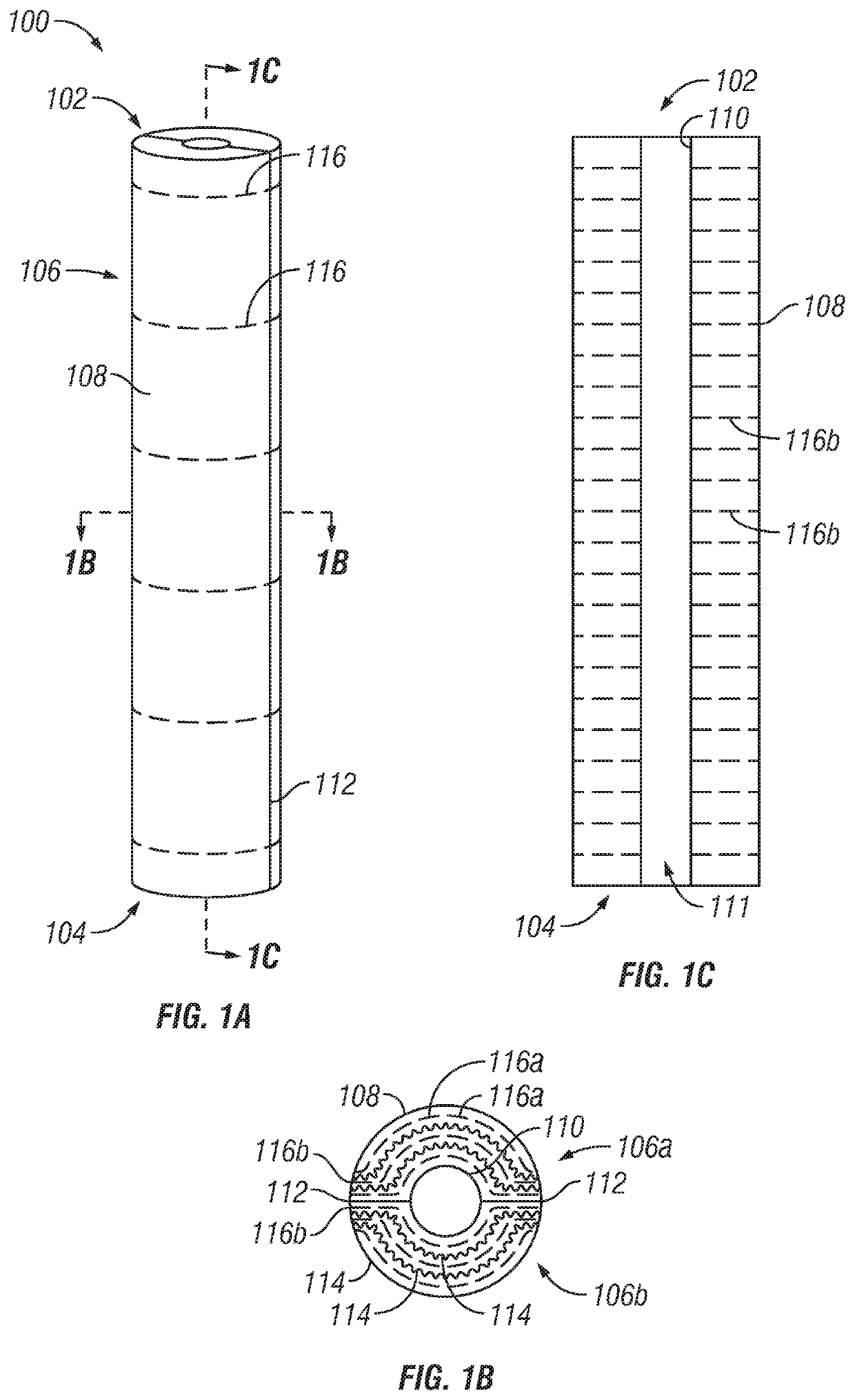
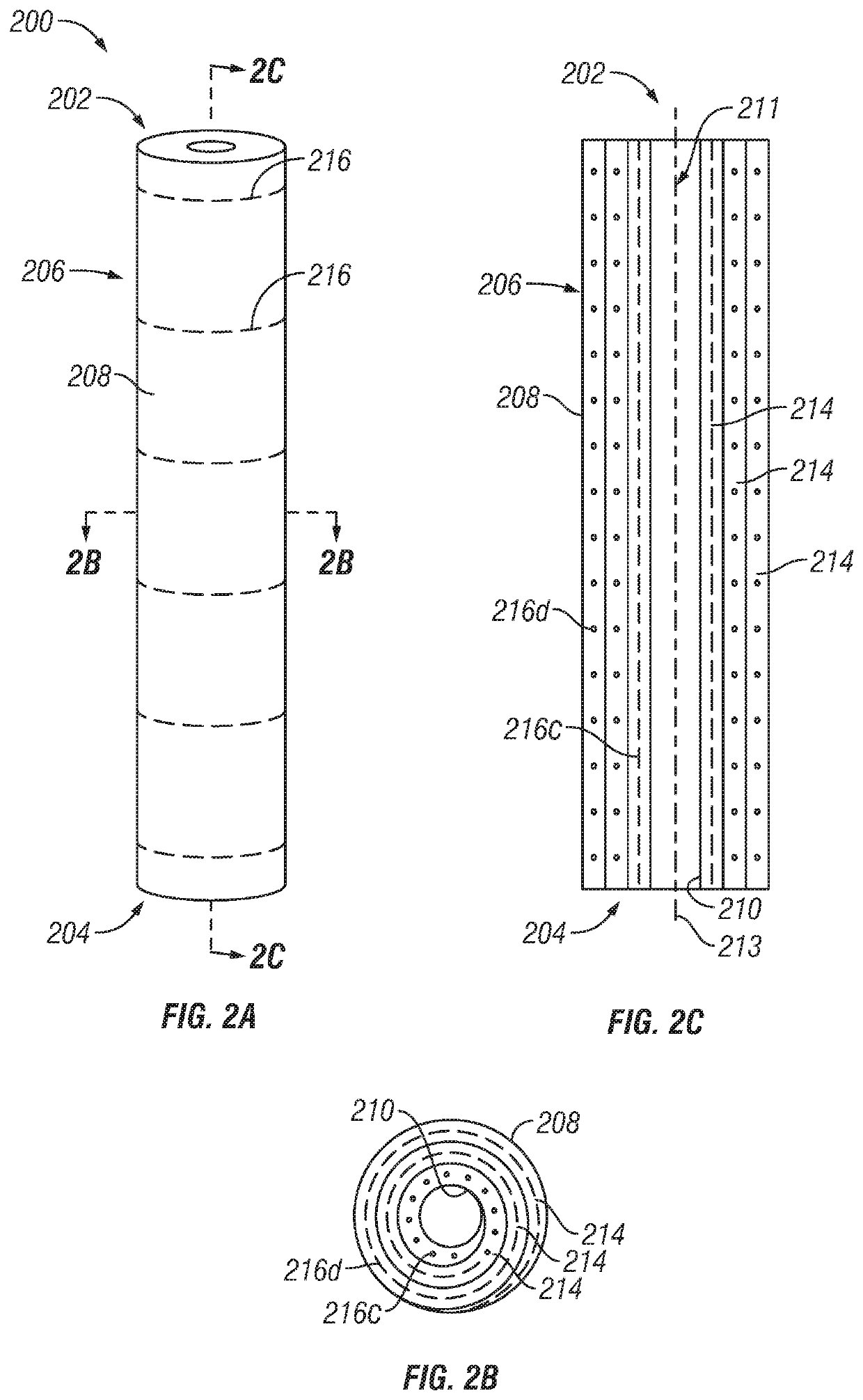
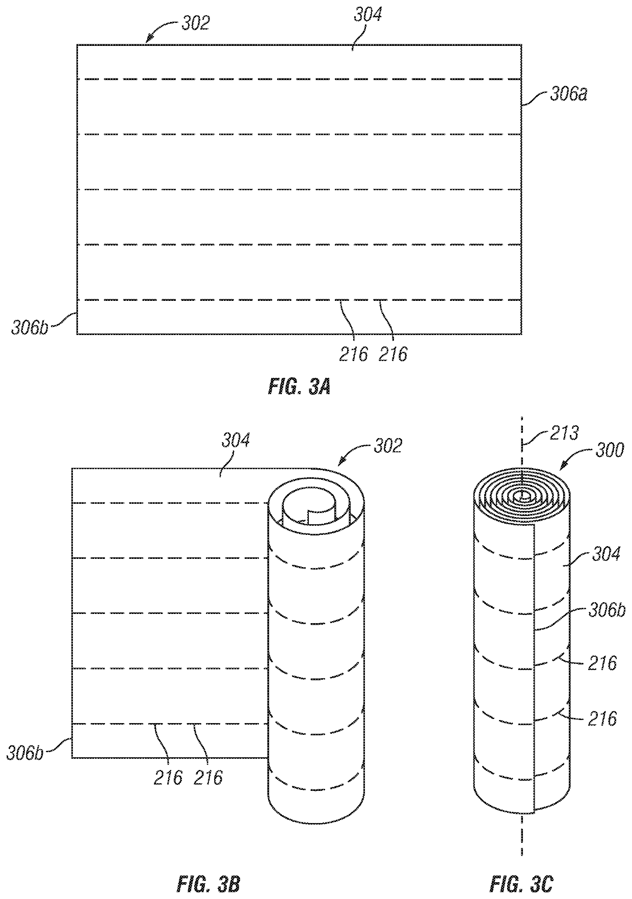
[0057]In a first embodiment, novel aspects of the present disclosure describe a method of forming a molded tool, an example of which is a mandrel used in drilling operations. The method comprises: shaping a compression mold material to form a shaped compression mold material, wherein the shaped compression mold material comprises a central axis extending through from a first end of the shaped compression mold material to a second end of the shaped compression mold material; heating the shaped compression mold material to form a heated compression mold material; and exerting an expansive force within an interior of the heated compression mold material to form the molded tool, wherein the expansive force includes a directional vector along the central axis.

[0058]In another aspect of the first embodiment, the method comprises: shaping a compression mold material to form a shaped compression mold material, wherein the shaped compression mold material comprises a central axis extending t...

second embodiment

[0079]In a second embodiment, novel aspects of the present disclosure describe a molded tool comprising: a first end; a second end separated from the first end by a sidewall formed from a heat-sensitive polymeric matrix; wherein the sidewall comprises an interior surface with a first strength and an exterior surface with a second strength, and wherein the first strength is higher than the second strength.

[0080]In another aspect of the second embodiment, novel aspects of the present disclosure describe a molded tool comprising: a first end; a second end separated from the first end by a sidewall formed from a heat-sensitive polymeric matrix; wherein the sidewall comprises an interior surface with a first strength and an exterior surface with a second strength, and wherein the first strength is higher than the second strength; and any one or more limitations selected from the following list:[0081]wherein the heat-sensitive polymeric matrix is a thermoset polymer;[0082]wherein the heat...


PUM

PropertyMeasurementUnit
heat-sensitiveaaaaaaaaaa
strengthaaaaaaaaaa
tensionaaaaaaaaaa

Abstract

A molded tool is formed from a compression mold material and a corresponding method of manufacture is disclosed. The molded tool has a first end, a second end separated from the first end by a sidewall formed from a heat-sensitive polymeric matrix. The sidewall has an interior surface with a first strength and an exterior surface with a second strength, the first strength being greater than the second strength. Further, the molded tool is formed by a method that includes exerting an expansive force within an interior of the compression mold material, the expansive force having a directional vector along the central axis.

Description

BACKGROUNDTechnical Field[0001]Novel aspects of the present disclosure relate to a molded tool and a corresponding method of manufacture. More particularly, the present disclosure is directed to an elongated, molded tool with improved strength in the radial direction, a feature attributable to a process that utilizes an expansive force originating from within the molded tool which has a directional vector oriented in the direction of and along a central axis of the molded tool.Background[0002]Examples of commonly utilized tools in the well drilling industry include bridge plugs and frac plugs. These tools are formed as elongated mandrels with slips on either end. Mandrels formed from metals provided desirable hardness, tensile strength, and compressive strength. However, tool components fabricated for downhole oil and gas operations are often drilled out rather than removed. Increased time and cost is required for drilling through metallic tool components. Accordingly, composite too...

Claims


Application Information

Patent Timeline
Patent Type & Authority Patents(United States)
IPC IPC(8): E21B33/12B29C70/56B29C43/20B29C43/02B29C70/44B29K105/08
CPCE21B33/1208B29C70/56B29C43/203B29C70/446B29C43/027E21B33/12B29K2105/0881
Inventor BARLOW, JOEL L.BARLOW, JOEL T.BARLOW, CHAPMAN
Owner WELLS FARGO BANK NAT ASSOC
Why Eureka
Try Eureka