
Lidar detection device of detecting close-distance obstacle and method thereof

a detection device and obstacle technology, applied in the field of obstacle detection technology, can solve the problems of difficulty in accurately establishing the obstacle model of the 77 g hz radar, limited number of obstacles detectable by the 24 g hz radar, and easy affecting of the camera, so as to reduce the required computation resource, facilitate the estimation of obstacle collision probability, and quickly complement the defect

Active Publication Date: 2020-04-28
AUTOMOTIVE RES & TESTING CENT
View PDF15 Cites 30 Cited by
  • Summary
  • Abstract
  • Description
  • Claims
  • Application Information

AI Technical Summary

Benefits of technology

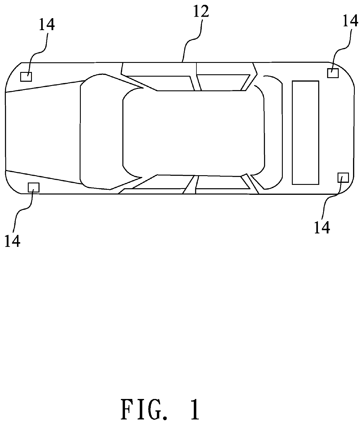
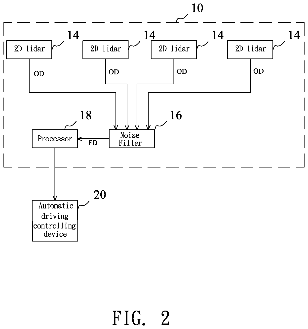
The present invention provides a lidar detection device and method for detecting close-distance obstacles. The device uses a Kalman filter and extrapolation to estimate and track the movement path of a dynamic obstacle, reducing computation resources and quickly complementing any defects caused by the absence of obstacle. The device also provides a border length of the dynamic obstacle to facilitate estimation of obstacle collision probability. Additionally, the device utilizes a two-dimensional lidar which has advantages of high data accuracy, broader field of view, and small blind spot, improving the close-distance detection capability of the vehicle and its accuracy for detecting blind spots.

Problems solved by technology

For example, the 77 G Hz radar is usually used for remote detection, and has a field of view (FOV) of 34 degrees and a blind spot within 2 meters, and is able to detect the distance of 100 meters away; however, but it is difficult for the 77 G Hz radar to establish an obstacle model accurately because of more noise and the limited FOV thereof.
The camera is usually used for remote detection, and has FOV of 90 degrees and a blind spot within 10 meters, and is able to detect the distance of 80 meters away; however, the camera is affected easily by heavy rain, dense fog, strong light and weather.
The 24 G Hz radar can be used for mid-distance detection, and has FOV of 80 degrees and is able to detect the distance of 40 meters away; however, the 24 G Hz radar is unable to capture the obstacle on the side (B-pillar) of the vehicle body, and the number of the obstacles detectable for the 24 G Hz radar is limited, and the data error of the 24 G Hz radar is as well as 77 G Hz radar which is harder to filter.
According to above-mentioned contents, radars and cameras are widely used in the autonomous vehicle but have drawbacks of more noise, high sensitivity to environmental factors and inability for close-distance detection.
When considering the overall sensors of autonomous vehicle, the platform which is arranged in pairs of 3D lidar will increases overall hardware cost.

Method used


Image

  • Lidar detection device of detecting close-distance obstacle and method thereof
  • Lidar detection device of detecting close-distance obstacle and method thereof
  • Lidar detection device of detecting close-distance obstacle and method thereof

Examples


Embodiment Construction

[0018]The following embodiments of the present invention are herein described in detail with reference to the accompanying drawings. These drawings show specific examples of the embodiments of the present invention. It is to be acknowledged that these embodiments are exemplary implementations and are not to be construed as limiting the scope of the present invention in any way. Further modifications to the disclosed embodiments, as well as other embodiments, are also included within the scope of the appended claims. These embodiments are provided so that this disclosure is thorough and complete, and fully conveys the inventive concept to those skilled in the art. Regarding the drawings, the relative proportions and ratios of elements in the drawings may be exaggerated or diminished in size for the sake of clarity and convenience. Such arbitrary proportions are only illustrative and not limiting in any way. The same reference numbers are used in the drawings and description to refer ...


PUM


Abstract

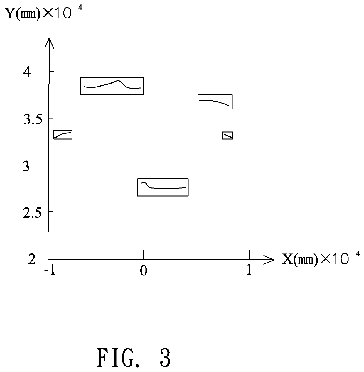
The lidar detection device uses four two-dimensional lidars to scan an obstacle, to obtain original point-cloud data corresponding to the obstacle, and the original point-cloud data includes a relative distance, a relative angle and a relative speed of the obstacle relative to the vehicle, Next, the point-cloud data is classified into at least one point-cloud group corresponding to the obstacle, and a border length of the obstacle is obtained according to a contour of the point-cloud group. Kalman filter and extrapolation are used to estimate and track a movement path of a dynamic obstacle, and transmit the relative speed and the border length of the dynamic obstacle to an automatic driving controlling device. According to the relative distance, a coordinate of the dynamic obstacle nearest the vehicle can be obtained and transmitted to the automatic driving controlling device efficiently.

Description

BACKGROUND OF THE INVENTION1. Field of the Invention[0001]The present invention relates to an obstacle detection technology, and more particular to a lidar detection device of detecting distance obstacle, and a method thereof.2. Description of the Related Art[0002]An autonomous vehicle is an intelligent vehicle installed with a sensing system which is able to sense road environment and use the sensed road, vehicle position and obstacle information to control the driving parameters of the vehicle, thereby driving the autonomous vehicle safely and reliably on the road to reach a predetermined destination. Therefore, the autonomous vehicle applies computer, sensing, communication, sensorfusion, artificial intelligence and automatic control technologies, and becomes the focus of research in countries around the world.[0003]The ambient sensors are indispensable devices in the autonomous vehicle, and include 77 G Hz radar, cameras, 24 GHz radar, three-dimensional (3D) lidar, and 2D lidar....

Claims


Application Information

Patent Timeline
Patent Type & Authority Patents(United States)
IPC IPC(8): G06F17/10G06T7/277G01S17/931G08G1/16G01S7/48G06V10/30G06V10/80
CPCG01S17/931G06T7/277G08G1/166G08G1/165G01S7/4808G06T2207/10028G06T2207/30261G01S17/87G01S17/42G01S17/58G01S2013/93271G01S2013/93272G01S2013/9323G06V20/58G06V10/30G06V10/80G06F18/25G06T5/70
Inventor SIAO, SIANG-MINCHEN, YING-RENHSU, LI-YOU
Owner AUTOMOTIVE RES & TESTING CENT
Learn More