
Flat emitters with stress compensation features

a flat emitter and stress compensation technology, applied in the field of xray tubes, can solve the problems of increasing the stress beyond the strength available in the emitter material, high acceleration, and high emission temperature, and achieve the effect of reducing the total stress

Active Publication Date: 2020-04-28
GENERAL ELECTRIC CO
View PDF57 Cites 0 Cited by
  • Summary
  • Abstract
  • Description
  • Claims
  • Application Information

AI Technical Summary

Benefits of technology

[0008]In the invention, a flat emitter is formed of an electron emissive material that includes one or more stress compensation features capable of reducing the total stress in the flat emitter due to thermal expansion and / or centrifugal acceleration force. The features of the emitter for reducing the total stress in the flat emitter are formed directly on the emitter, are formed on the support structure for the emitter and connected to the emitter, or a combination thereof.
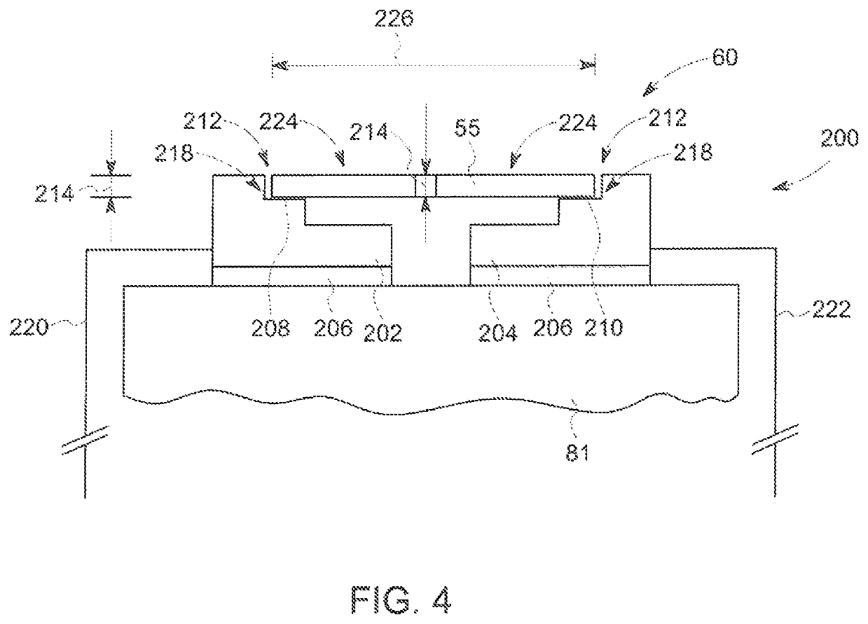
[0009]According to one aspect of an exemplary embodiment of the invention, the emitter can be formed with a structure to mitigate the effect of thermal stresses or expansion of the emitter. These features can be included in the structure of the emitter or on the support structure for the emitter and accommodate the expansion of the emitter as a result of the heating of the emitter due to the current passing through the emitter (Joule heating). Different exemplary embodiments of the features reduce the effects of thermal stress or expansion on the emitter include: an emitter with one end fixed and the other end attached with a compliant region outside the emission region that does not carry current, an emitter with one end fixed and the other end allowed to slide freely in the direction of the acceleration that does not carry current, a thermal expansion compensation feature included in one or both ends of the emitter, and / or a thermal expansion compensation sub-structure disposed on the support structure for the emitter and to which the emitter is attached.
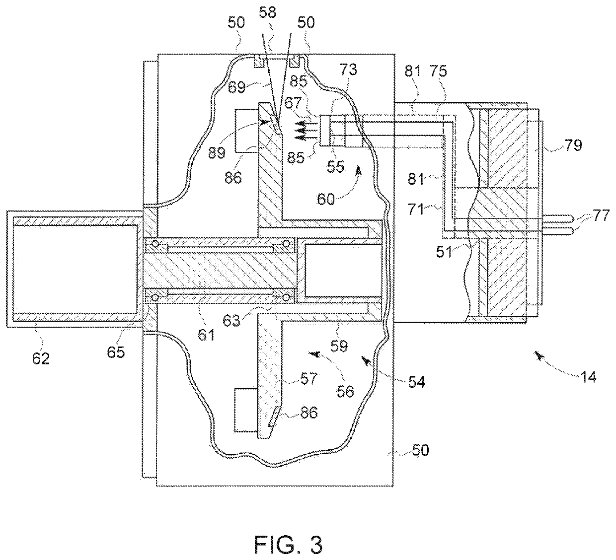
[0010]According to another aspect of an exemplary embodiment of the invention, the emitter can be formed with a structure to mitigate the effect of the centrifugal forces exerted on the emitter as it is rotated during use. These features can be included in the structure of the emitter or on the support structure for the emitter and accommodate the expansion of the emitter as a result of the centrifugal forces exerted on the emitter. Different exemplary embodiments of the features that lower the stresses due to centrifugal acceleration on the emitter include: an electrically isolated contact in the emission region of the emitter to react centrifugal force(s), an extension from the emission region on the emitter to an electrically isolated support to react centrifugal force(s), and / or a series of shorter emitters making up the full emission area.
[0011]Therefore, with one or more of these features includes within the emitter structure and / or connected between the emitter and the emitter support structure on the cathode, in certain exemplary embodiments of the invention, the features can function to prolong the life of an X-ray tube by avoiding short circuits from forming between adjacent ribbons of the flat emission surface of the emitter as a result of the thermal and centrifugal forces acting on the emitter, while also enabling longer emission areas and higher emission and rotation speeds for CT with longer times between required servicing of the X-ray tubes.

Problems solved by technology

Typical flat emitters are not capable of operating in the regime of combined long emissive lengths, high emission temperatures, and high acceleration forces.
In particular, long emissive lengths for the flat emission surface and high accelerations increase the stress beyond the strength available in the emitter material at high emission temperatures.
For long flat emitters operating at high temperatures with high centrifugal acceleration force exerted on the emitter, the combination of the high centrifugal force, thermal strains, and reduced material properties results in the emitter deforming in the direction of the centrifugal force, which can cause the slots dividing the emission surface to close, such that adjacent ribbons come into contact with one another.

Method used


Image

  • Flat emitters with stress compensation features
  • Flat emitters with stress compensation features
  • Flat emitters with stress compensation features

Examples


Embodiment Construction

[0027]In the following detailed description, reference is made to the accompanying drawings that form a part hereof, and in which is shown by way of illustration specific embodiments, which may be practiced. These embodiments are described in sufficient detail to enable those skilled in the art to practice the embodiments, and it is to be understood that other embodiments may be utilized and that logical, mechanical, electrical and other changes may be made without departing from the scope of the embodiments. The following detailed description is, therefore, not to be taken in a limiting sense.

[0028]Exemplary embodiments of the invention relate to an X-ray tube including an increased emitter area to accommodate larger emission currents in conjunction with microsecond X-ray intensity switching in the X-ray tube. An exemplary X-ray tube and a computed tomography system employing the exemplary X-ray tube are presented.

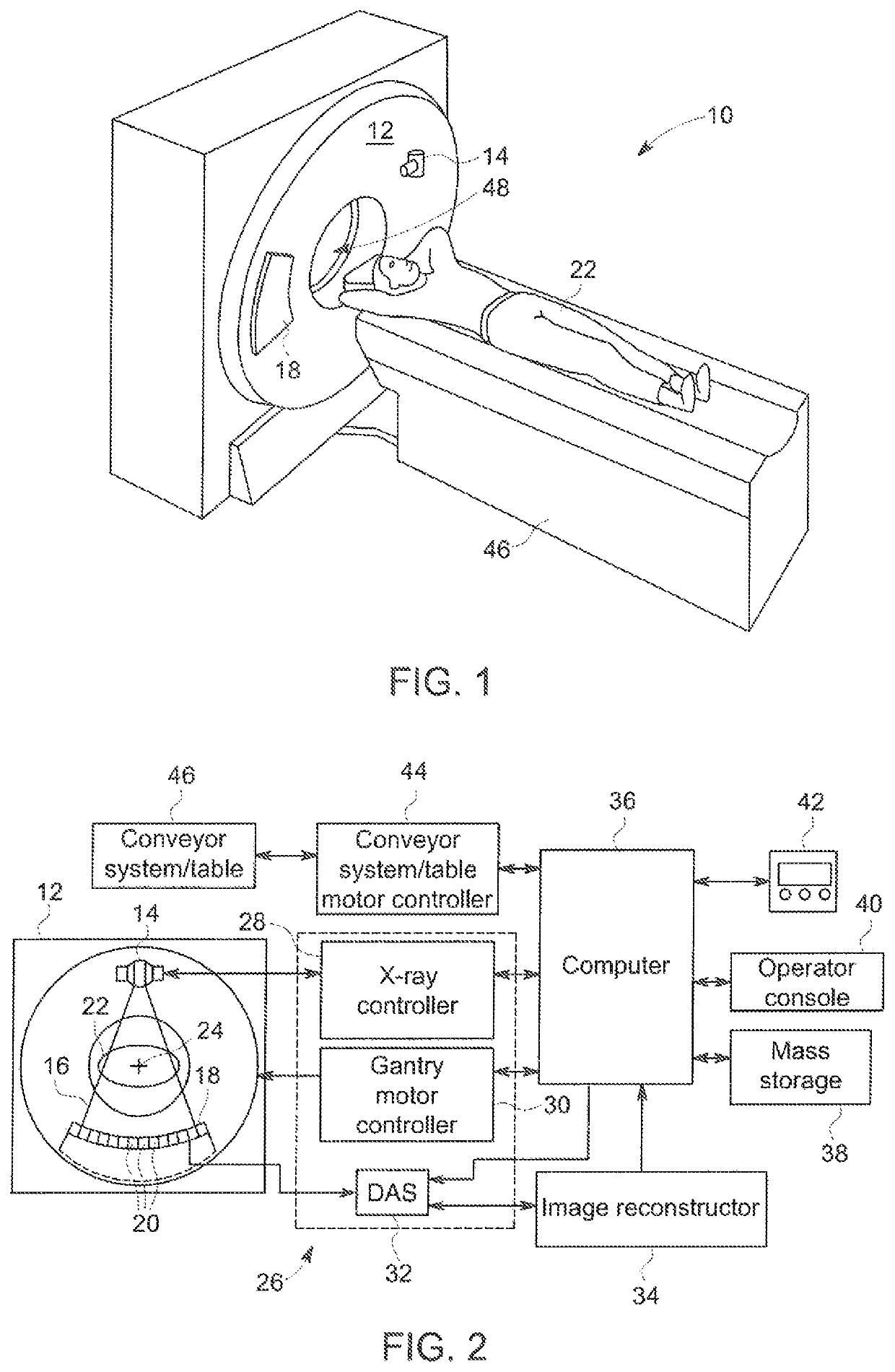
[0029]Referring now to FIGS. 1 and 2, a computed tomography (CT) ima...


PUM

PropertyMeasurementUnit
temperaturesaaaaaaaaaa
atomic numberaaaaaaaaaa

Abstract

A flat emitter for uses within an x-ray tube is formed of an electron emissive material that includes one or more stress compensation features capable of reducing the total stress in the flat emitter due to thermal expansion and / or centrifugal acceleration force. The one or more stress compensation features of the flat emitter for reducing the total stress in the flat emitter are formed directly on the flat emitter, are formed on the support structure for the flat emitter and connected to the flat emitter, or a combination thereof.

Description

BACKGROUND OF THE INVENTION[0001]The invention relates generally to x-ray tubes, and more particularly to structures for emitters utilized in an x-ray tube that exerts thermal expansion and high centrifugal force stresses on the emitter.[0002]X-ray systems may include an x-ray tube, a detector, and a support structure for the x-ray tube and the detector. In operation, an imaging table, on which an object is positioned, may be located between the x-ray tube and the detector. The x-ray tube typically emits radiation, such as x-rays, toward the object. The radiation, passes through the object on the imaging table and impinges on the detector. As radiation passes through the object, internal structures of the object cause spatial variances in the radiation received at the detector. The detector then emits data received, and the system translates the radiation variances into an image, which may be used to evaluate the internal structure of the object. The object may include, but is not l...

Claims


Application Information

Patent Timeline
Patent Type & Authority Patents(United States)
IPC IPC(8): H01J35/02H01J35/06
CPCH01J35/02H01J35/064H01J35/06H01J35/025H01J2201/2803H01J2235/06
Inventor LAMPE, EVANEMACI, EDWARDMARCONNET, ANDREWHEBERT, MICHAELUTSCHIG, MICHAEL
Owner GENERAL ELECTRIC CO
Learn More