Automatic tilting vehicle

a technology of automatic tilting and vehicle, which is applied in the direction of cycle equipment, transportation and packaging, transportation and packaging, etc., can solve the problems of difficult to precisely control the tilt angle of the vehicle with good response, limited angular range of the vehicle, and large energy consumption of the actuator, so as to reduce the effect of low pass filter processing, improve the ride comfort of the vehicle, and quickly change the target tilt angle

Active Publication Date: 2020-05-05
TOYOTA JIDOSHA KK
View PDF33 Cites 1 Cited by
  • Summary
  • Abstract
  • Description
  • Claims
  • Application Information

AI Technical Summary

Benefits of technology

[0013]The present disclosure provides an automatic tilting vehicle improved to reduce an energy consumption by an actuator as compared with the prior art by calculating a target tilt angle of the vehicle in consideration of a lateral acceleration of the vehicle caused by the gyro moments acting on the wheels.
[0027]According to the above aspect, in a situation where the setting device sets to limit the magnitude of the target tilt angle, low pass filter processing can be performed on any one of the wheel speeds, the gyro moments, and the lateral acceleration of the vehicle caused by the gyro moments. Therefore, a sudden change in the tilt angle of the vehicle can be prevented so that the ride comfort of the vehicle can be improved. On the other hand, in a situation where the setting device does not set to limit the magnitude of the target tilt angle, it is possible to reduce the effect of the low pass filter processing and quickly change the target tilt angle so that the target tilt angle does not lag and becomes a value suitable for the running condition of the vehicle. Therefore, for example, even when a vehicle speed and / or a steering operation amount of the driver rapidly changes, a tilt angle of the vehicle can be controlled so that it becomes an angle suitable for the running condition of the vehicle, which enables to secure good turning performance.

Problems solved by technology

Therefore, it is difficult to precisely control a tilt angle of the vehicle with good response so that the tilt angle of the vehicle conforms to a target tilt angle.
Therefore, a range of the vertical movement of each tie rod is limited to a narrow range and, accordingly, an angular range capable of tilting the vehicle is limited.
In an automatic tilting vehicle, particularly an improved automatic tilting vehicle having a large tiltable angular range, as described below, there is a problem that an energy consumed by the actuator is large and a tilt angle of the vehicle cannot necessarily be precisely controlled to the target tilt angle.
Therefore, since a deviation between a target lateral acceleration and the actual lateral acceleration of the vehicle becomes large, even if the vehicle tilting device is controlled so that the tilt angle of the vehicle becomes a target tilt angle, it is difficult to accurately control the tilt angle of the vehicle to the target tilt angle.
Further, when the positional relationship between the swing member and the pair of tie rods changes, elastic deformation amounts of elastic members elastically urging the swing member and the pair of tie rods to their positions in the standard state of the vehicle change from the original values that are elastic deformation amounts when the positional relationship does not change, which causes to accumulate energy.
Therefore, even if the vehicle tilting device is controlled so that the tilt angle of the vehicle becomes a target tilt angle, it is difficult to accurately control the tilt angle of the vehicle to the target tilt angle.
The reason why an energy consumed by the actuator is large and it is difficult to accurately control the tilt angle of the vehicle to the target tilt angle is the fact that a lateral acceleration of the vehicle caused by the gyro moments are not taken into account when calculating a target tilt angle of the vehicle.

Method used


Image

  • Automatic tilting vehicle
  • Automatic tilting vehicle
  • Automatic tilting vehicle

Examples


first embodiment

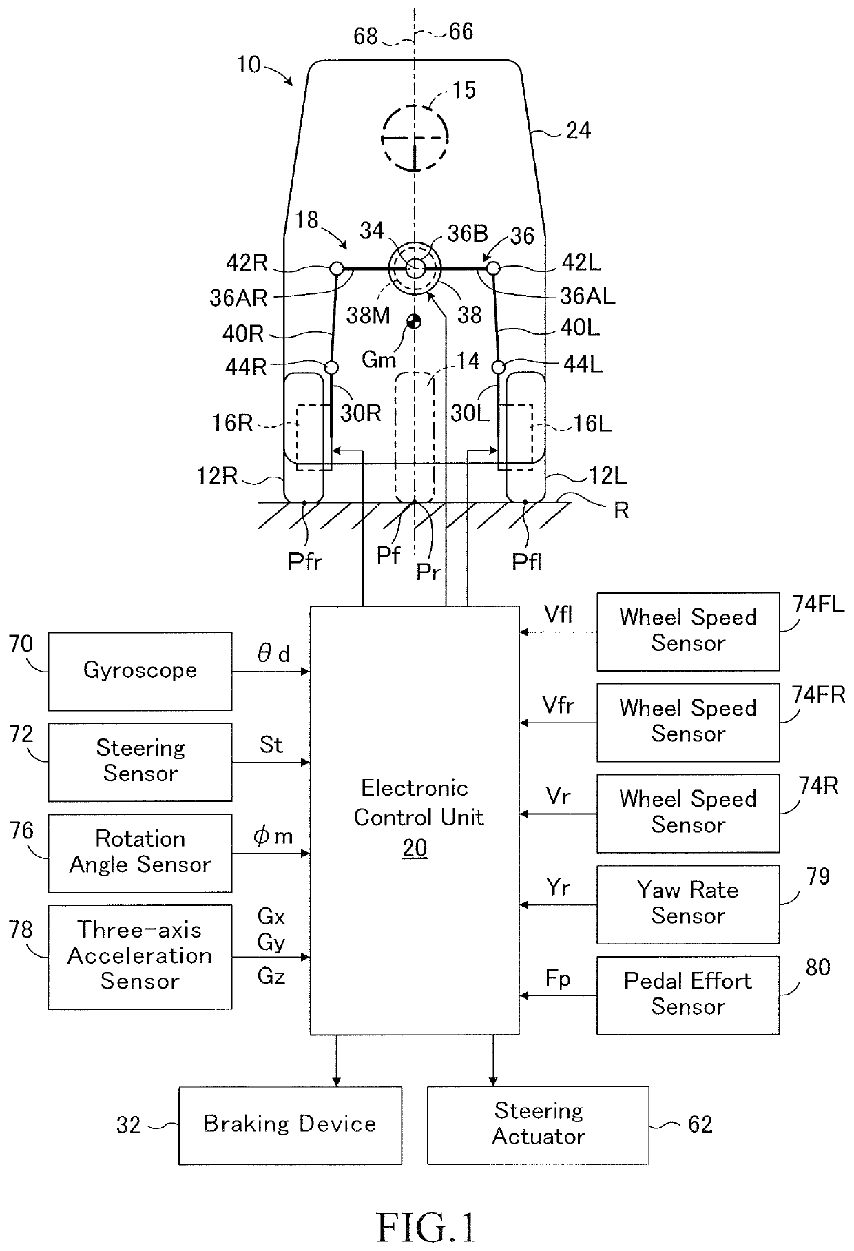
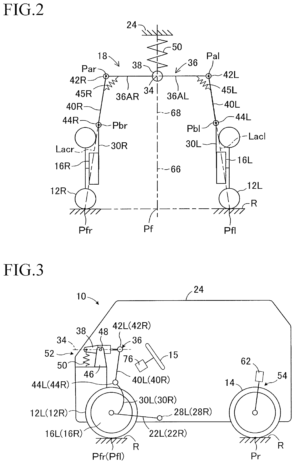
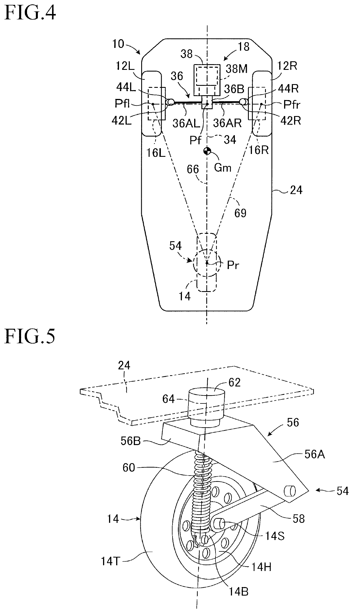
[0050]In FIGS. 1 to 4, an automatic tilting vehicle 10 according to an embodiment of the present disclosure is a tricycle vehicle with a capacity of one which includes a pair of front wheels 12L and 12R that are non-steered drive wheels, and a rear wheel 14 that is a steered driven wheel. The front wheels 12L and 12R are spaced apart from each other in the lateral direction and are rotatably supported about a rotation axis (not shown) by corresponding knuckles (wheel carriers) 16L and 16R.

[0051]In the embodiment, a camber of the front wheels 12L and 12R is a neutral camber, so that a camber angle of the front wheels at the time when the vehicle 10 is not turning. It should be noted that the camber of the front wheels may be a negative camber or may be a positive camber. The rear wheel 14 is located rearward of the front wheels and steered in a steer-by-wire manner according to an amount of operation of a steering wheel 15 by a driver, as will be described in detail later. In FIG. 1 ...

second embodiment

[0138]FIG. 18 is a flowchart showing a control routine for controlling the tilt angle of the vehicle according to the second embodiment of the automatic inclined vehicle according to the present invention. In FIG. 18, the same step numbers as those shown in FIG. 7 are assigned to the same steps as those shown in FIG. 7. Further, the configuration of the second embodiment relating to the control routine of the tilt angle of the vehicle and the control routine of the steered angle of the rear wheel is the same as that of the first embodiment.

[0139]As can be understood from the comparison between FIG. 18 and FIG. 7, in the second embodiment, step 90 in the first embodiment is not executed, and upon completion of step 80, the control of the tilt angle proceeds to step 100. Therefore, since the magnitude of the target tilt angle θt of the vehicle is not limited, the magnitude of the target tilt angle θt may become larger than the maximum allowable tilt angle θamax.

[0140]In the second emb...

third embodiment

[0144]FIG. 19 is a schematic configuration diagram showing a third embodiment of the automatic inclined vehicle according to the present invention. In FIG. 19, the same reference numerals as those denoted in FIG. 1 are given to the same members as those shown in FIG. 1.

[0145]As can be understood from the comparison between FIG. 19 and FIG. 1, in the third embodiment, the vehicle 10 is provided with a setting switch 81 operated by the occupant, and the setting switch 81 functions as a setting device for setting whether or not to limit a magnitude of the target tilt angle θt of the vehicle. This switch is switched between on and off, and when it is on, it is set to limit the magnitude of the target tilt angle θt.

[0146]In the third embodiment, when the setting switch 81 is on, a tilt angle θ of the vehicle 10 and a steered angle δr of the rear wheel 14 are controlled in the same manner as in the above-described first embodiment. On the other hand, when the setting switch 81 is off, a t...


PUM


Abstract

An automatic tilting vehicle is provided that includes left and right front wheels supported by knuckles, a steerable rear wheel, a vehicle tilting device, and a control unit. The vehicle tilting device includes a swing member, a tilt actuator for swing the swing member, and a pair of tie rods pivotally attached to the swing member and the knuckles. The control unit calculates a target lateral acceleration of the vehicle, estimates a lateral acceleration of the vehicle caused by the gyro moments of the wheels and calculates a target tilt angle of the vehicle based on a sum of the target lateral acceleration and the lateral acceleration caused by the gyro moments.

Description

CROSS-REFERENCE TO RELATED APPLICATION[0001]The disclosure of Japanese Patent Application NO. JP2017-53346 filed on Mar. 17, 2017 is incorporated by reference in its entirety.BACKGROUND1. Technical Field[0002]The present disclosure relates to an automatic tilting vehicle that automatically tilts (self inclines) to the inside of a turn when turning.2. Description of the Related Art[0003]An automatic tilting vehicle has a vehicle tilting device, and the vehicle is automatically tilted to the inner side of a turn by the vehicle tilting device at the time of turning. For example, International Publication No. 2012 / 049724 describes an automatic tilting vehicle that includes a pair of front wheels spaced laterally, a swing type vehicle tilting device, and a control unit that controls the vehicle tilting device, and the pair of front wheels are rotatably supported by corresponding knuckles. The vehicle tilting device includes a swing member swingable about a swing axis extending in a longi...

Claims


Application Information

Patent Timeline
Patent Type & Authority Patents(United States)
IPC IPC(8): B60G17/016B62K5/027B60G17/0195B62K5/05B62J45/40B62D9/02B62K5/10B62K5/08B60G17/018B60G21/00B60G21/08
CPCB62K5/08B62D9/02B62K5/027B60G17/0162B60G17/0195B62K5/10B60G21/08B60G21/007B60G17/0182B60G2300/122B60G2400/0511B60G21/005B60G2202/42B60G2400/104B60G2400/0521B60G2400/106B62K5/05B60G2400/0523B60G2300/45B60G2400/34B60G2400/41B60G2400/102B60G2401/28B60G2400/39B60G2600/20B60G2400/204B60G2400/208B60G2401/904B62J45/40B60G2600/604B60G2800/70B60G2400/302B60G2400/40B60G2800/012B60G3/18B62D7/20B62K25/00B62J45/4151B62J45/414
Inventor KIMURA, YUKIHIDEYANO, TOSHIHIDEYAMAMOTO, JUNROUNAGASAWA, TAKU
Owner TOYOTA JIDOSHA KK
Why Eureka
Try Eureka