Optical lens, and light unit and lighting device having same

a technology of optical lenses and light units, applied in the field of optical lenses, can solve the problems of very low power consumption of light emitting diodes, and achieve the effects of improving the incidence efficiency of optical lenses, reducing noise, and improving light uniformity

Active Publication Date: 2020-05-05
SUZHOU LEKIN SEMICON CO LTD
View PDF22 Cites 6 Cited by
  • Summary
  • Abstract
  • Description
  • Claims
  • Application Information

AI Technical Summary

Benefits of technology

[0036]The embodiment may reduce noise such as hot spot caused by light emitted from the optical lens.
[0037]The embodiment may improve the light uniformity in the light unit.
[0038]The embodiment may improve the incidence efficiency of the optical lens by the light emitting device having the reflective sidewalls.
[0039]The embodiment may improve a uniformity of light on the side view type light unit.
[0040]The embodiment may improve the reliability of a light unit having an optical lens and a lighting apparatus having the same.
[0041]The embodiment may reduce a problem of an interference light due to a tilting of the optical lens.

Problems solved by technology

Since the light emitting diode generates light by using a semiconductor device, the light emitting diode consumes very low power, as compared to an incandescent lamp which generates light by heating tungsten or a phosphor lamp which generates light by colliding ultraviolet rays generated through high pressure discharge with a phosphor.

Method used


Image

  • Optical lens, and light unit and lighting device having same
  • Optical lens, and light unit and lighting device having same
  • Optical lens, and light unit and lighting device having same

Examples


first embodiment

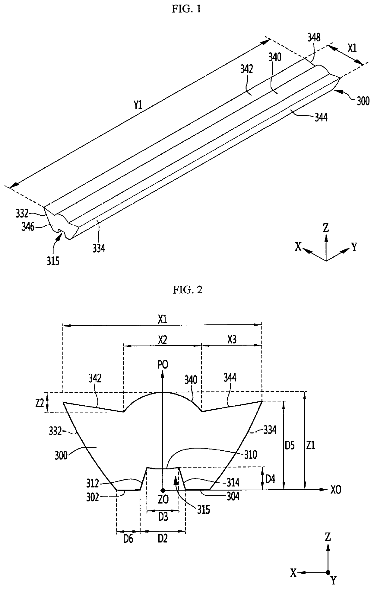
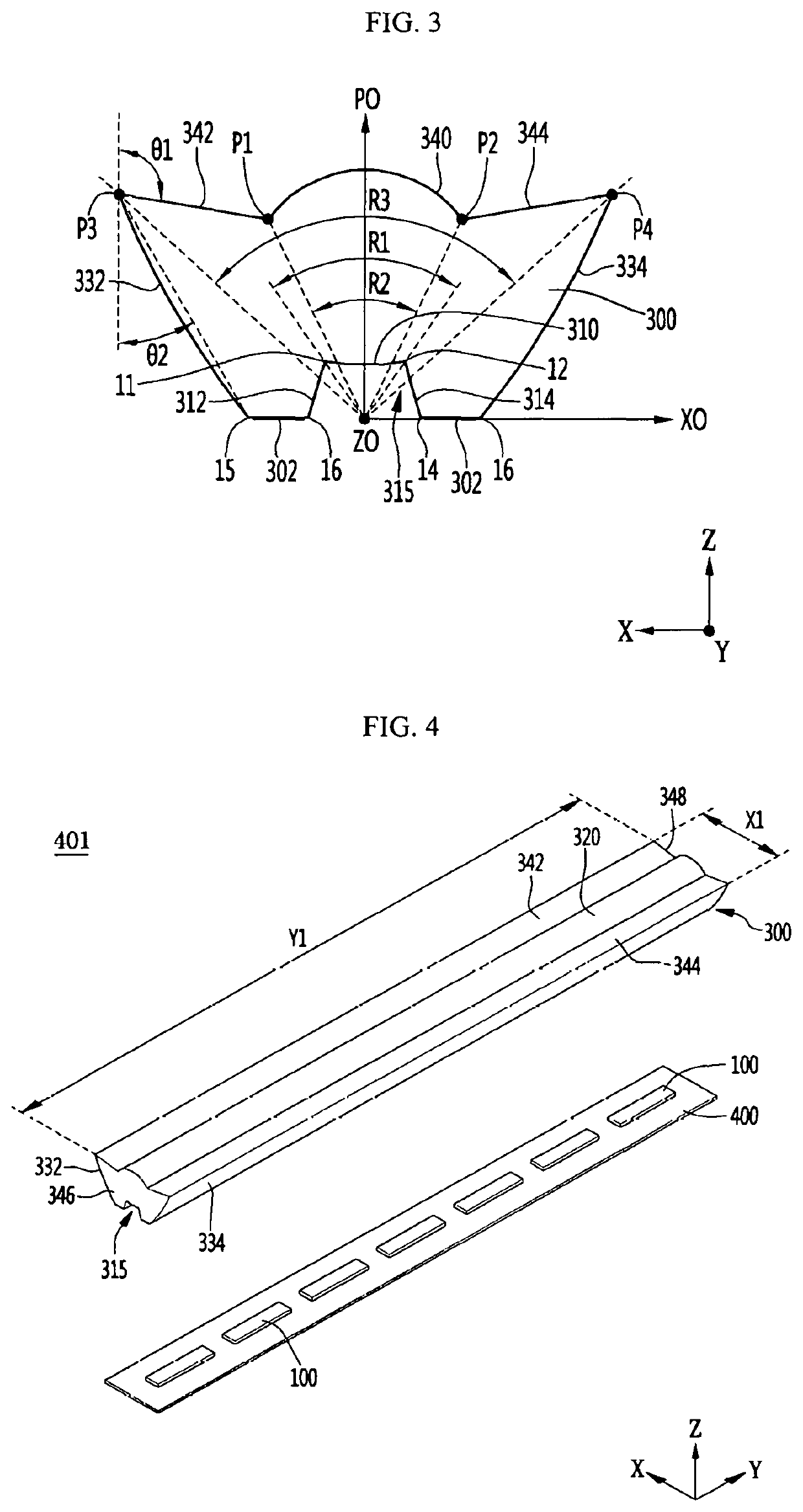
[0091]FIG. 1 is a perspective view showing the optical lens according to the first embodiment, FIG. 2 is a side sectional view of the optical lens of FIG. 1, and FIG. 3 is a plan view of the optical lens shown in FIG. 1, and FIG. 4 is a perspective view showing a light unit having the optical lens of FIG. 1.

[0092]Referring to FIGS. 1 to 4, the optical lens 300 according to the embodiment is a transparent body and may have a long length in one direction. In the optical lens 300, a length direction may be a second axis Y direction of the body, a width direction may be a first axis X direction of the body, and a thickness or vertical direction may be a third axis Z direction of the body. The first axis X direction and the second axis Y direction are orthogonal to each other and the third axis Z direction may be orthogonal to the first and second axes X and Y directions.

[0093]The length Y1 of the optical lens 300 in the second axis Y direction may be greater than the width X1 of the fir...

second embodiment

[0152]FIG. 16 is a perspective view of a light unit having an optical lens according to the second embodiment, FIG. 17 is a side sectional view of the optical lens of FIG. 16, and FIG. 18 is a view for explaining an incident surface and an exit surface of the optical lens of FIG. 17. In describing the second embodiment, the same configuration as that of the first embodiment described above may be selectively applied to the second embodiment with reference to the description of the first embodiment.

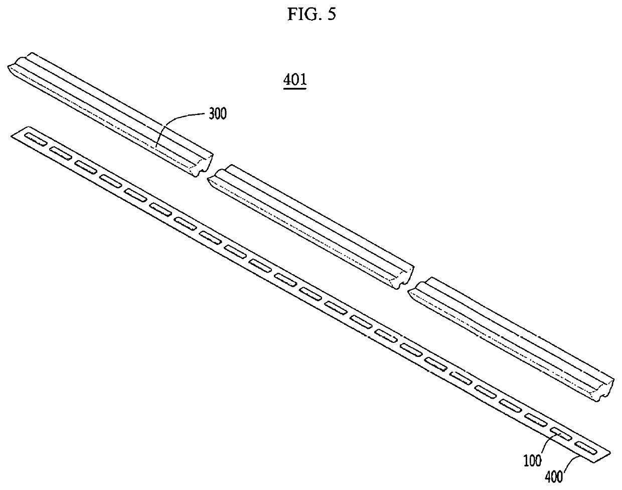
[0153]Referring to FIGS. 16 to 18, the light unit 401 includes the optical lens 301 according to the second embodiment. The light unit 401 includes a circuit board 400, a plurality of light emitting devices 100, and an optical lens 301.

[0154]Referring to FIGS. 17 and 18, the optical lens 301 includes a plurality of bottom surfaces 302 and 304, a recess 315 between the plurality of bottom surfaces 302 and 304, a plurality of incident surfaces 320, 322, and 324 on an outer sides of the reces...

third embodiment

[0172]FIG. 22 is a perspective view of a light unit having an optical lens according to the third embodiment, FIG. 23 is a view showing an optical lens of the light unit of FIG. 22, FIG. 24 is an assembled side cross-sectional view of the light unit of FIG. 22, and FIG. 25 is a view showing support protrusions of the optical lens in the light unit of FIG. 22.

[0173]Referring to FIGS. 22 to 25, the light unit 401 includes a circuit board 400, a plurality of light emitting devices 100 according to an embodiment disposed on the circuit board 400, and a plurality of optical lenses 301A on the circuit board 400.

[0174]The light emitting device 100 may be disposed between the optical lens 301A and the circuit board 400. The light emitting device 100 may be disposed at a higher than the bottom surfaces 302 and 304 of the optical lens 301A.

[0175]The length and the width of the optical lens 301A will be described with reference to the configuration of FIG. 16. In the optical lens 301A, the sec...


PUM

PropertyMeasurementUnit
length Y1aaaaaaaaaa
length Y1aaaaaaaaaa
widthaaaaaaaaaa

Abstract

An optical lens in embodiment discloses: first and second bottom surfaces spaced apart from each other and having a longer in a second axial direction than to a first axial direction at a lower portion of a transparent body; a concave recess between the first and second bottom surfaces; plurality of incident surfaces having a first incident surface on the recess, second and third incident surfaces corresponding to each other on both sides of the recess; first and second total reflective surfaces disposed on opposite sides of the body; and a first exit surface on the body; and second and third exit surfaces on a both sides the first exit surface.

Description

CROSS-REFERENCE TO RELATED PATENT APPLICATIONS[0001]This application is a U.S. National Stage Application under 35 U.S.C. § 371 of PCT Application No. PCT / KR2017 / 001784, filed Feb. 17, 2017, which claims priority to Korean Patent Application No. 10-2016-0018337, filed Feb. 17, 2016, and Korean Patent Application No. 10-2016-0125539, filed Sep. 29, 2016, whose entire disclosures are hereby incorporated by reference.TECHNICAL FIELD[0002]The present invention relates to an optical lens.[0003]The present invention relates to a light unit having an optical lens and a lighting device.BACKGROUND ART[0004]A light emitting device, for example, a light emitting diode (LED), is a type of a semiconductor device which converts electrical energy into light. The light emitting diode replaces an existing phosphor lamp, incandescent lamp, or the like and is considered as a next-generation light source.[0005]Since the light emitting diode generates light by using a semiconductor device, the light emi...

Claims


Application Information

Patent Timeline
Patent Type & Authority Patents(United States)
IPC IPC(8): F21K9/69F21V17/00G02B19/00G02B3/00H01L33/58H05K1/18F21V5/04F21S4/26F21V7/00H01L33/50H01L25/075H01L33/56F21Y103/10F21Y115/10
CPCF21V5/045F21K9/69F21S4/26F21V17/005G02B19/00F21V7/0091H01L33/58H05K1/181G02B3/00F21V17/002H01L33/56F21Y2103/10H05K2201/10106H01L33/505F21Y2115/10F21V7/0008H01L33/507H01L25/0753F21V5/04G02B19/0028G02B19/0066
Inventor KANG, MIN SOO
Owner SUZHOU LEKIN SEMICON CO LTD
Why Eureka
Try Eureka