Phase accumulation digital-to-analog converter (DAC)

a digital-to-analog converter and phase accumulation technology, applied in the field of digital-to-analog conversion circuitry, can solve the problems of occupying a large portion of the overall area, increasing power consumption and area of the dacs, and large analog components, etc., and achieves small area, small configuration, and high resolution.

Active Publication Date: 2020-05-05
IQ ANALOG
View PDF2 Cites 0 Cited by
  • Summary
  • Abstract
  • Description
  • Claims
  • Application Information

AI Technical Summary

Benefits of technology

[0013]Disclosed herein is a phase accumulation digital-to-analog converter (DAC) using a digital-to-time converter (DTC), a phase-to-time logic (PTL), and a time-to-voltage converter (TVC). The design primarily uses digital cells while keeping the analog components to a minimum. Since the area and power consumption do not scale with a power of 2, as in conventional designs, the resolution can be increased, as the configuration is very flexible. The circuitry can operate at gigahertz (GHz) frequencies with a single 0.8 volt (V) supply, resulting in a very small area, lower power consumption, and simple layout.
[0014]The DTC is made up of delay stages or accumulators that are made up of buffers (delay elements), capacitors, and switches. The capacitors are sized depending on the data bit that activates it, for example, C1=Cx, C2=2*Cx, C3=3*Cx, . . . , CN=2N-1*Cx where Cx is the unit capacitance. When the switch is turned on by a data bit, the capacitor is grounded. This capacitor is charged and discharged as the clock transitions through the accumulator, providing a delay proportional to the weight of the capacitor. As no extra static power is consumed, this results in a considerable power savings.

Problems solved by technology

However, the power consumption and area of the DACs increase with a power of 2 for every extra bit of resolution to maintain the same linearity.
The sizes of the analog components are quite large and take up a huge portion of the overall area.
However, in low voltage technologies where the supply voltage is limited to 0.8V (volts), the voltage headroom is insufficient to stack several transistors in series.
Hence, cascading transistors would require higher potential voltage supplies (1.2V and above), which is an additional design and layout effort.

Method used


Image

  • Phase accumulation digital-to-analog converter (DAC)
  • Phase accumulation digital-to-analog converter (DAC)
  • Phase accumulation digital-to-analog converter (DAC)

Examples


Embodiment Construction

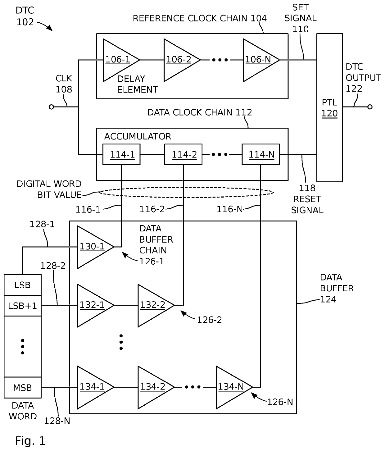
[0035]FIG. 1 is a schematic block diagram of digital-to-time converter for a phase accumulation digital-to-analog converter (DAC). The DAC comprises a digital-to-time converter (DTC) 102, which comprises a reference clock chain 104. The reference clock chain 104, in turn, comprises N number of series connected delay elements 106-1 through 106-N, where N is an integer greater than or equal to 1. In one aspect the delay elements are buffers, a circuit that is well known in the art. However, the delay elements of the reference clock chain, the data clock chain, and data buffer (described below) are not limited to any particular delay mechanism, and may be enabled using active, passive, or a combination of active and passive components. The reference clock chain 104 has an input on line 108 to accept a clock signal (CLK) with a leading clock edge and an output on line 110 to supply a set signal representing a first delay of the leading clock edge. As shown in FIG. 5, the first delay dur...


PUM


Abstract

A phase accumulation digital-to-analog converter (DAC) is provided. A digital-to-time converter (DTC), including a reference clock chain with N number of series connected delay elements, accepts a clock signal with a leading clock edge and supplies a set signal representing a first delay of the leading clock edge. A data clock chain including N number of series connected accumulators, accepts the clock signal with the leading clock edge, accepts a binary coded digital word, and supplies a reset signal representing a second delay of the leading clock edge, responsive to the digital word. A phase-to-time logic (PTL) receives the set and reset signals and supplies a DTC output signal representing the difference in delay between the set and reset signals. A time-to-voltage converter (TVC) charges a load capacitor every clock period in response to the DTC output signal to supply an analog output signal.

Description

RELATED APPLICATIONS[0001]Any and all applications, if any, for which a foreign or domestic priority claim is identified in the Application Data Sheet of the present application are hereby incorporated by reference under 37 CFR 1.57.BACKGROUND OF THE INVENTION1. Field of the Invention[0002]This invention generally relates to digital-to-analog conversion circuitry and, more particularly, to a digital-to-analog converter (DAC) that operates on the principle of digital-to-time phase accumulation.2. Description of the Related Art[0003]At the time of this writing, gigahertz state-of-the-art DACs use a current-steering architecture to operate at high speeds with sufficient linearity. However, the power consumption and area of the DACs increase with a power of 2 for every extra bit of resolution to maintain the same linearity. The sizes of the analog components are quite large and take up a huge portion of the overall area. To obtain a high linearity, the output impedance of the DAC must b...

Claims


Application Information

Patent Timeline
Patent Type & Authority Patents(United States)
IPC IPC(8): H03M1/82
CPCH03M1/82
Inventor SEBASTIAN, SUNIT PAUL
Owner IQ ANALOG
Why Eureka
Try Eureka