Manual actuators for thermoelectric modules and related methods

a technology of thermoelectric modules and manual actuators, applied in the direction of diagnostic recording/measuring, white arms/cold weapons, butts, etc., can solve the problems of battery death, particularly problematic,

Active Publication Date: 2020-05-12
GRACE ENG
View PDF41 Cites 0 Cited by
  • Summary
  • Abstract
  • Description
  • Claims
  • Application Information

AI Technical Summary

Benefits of technology

[0013]In a further embodiment, the device can be an aiming device including a light source powered by the thermoelectric module. The aiming device can be distal from the grasping element. The light source can illuminate a sight element of a projectile shooting device to enhance visibility of the sight element in a variety of ambient lighting conditions, optionally in low light conditions. With the aiming device, a user can selectively illuminate a sight element of a projectile shooting device, optionally with the user's own body heat, to assist aiming the projectile shooting device during a shooting activity.
[0028]In still another, further embodiment, a method is provided including: mounting a grasping element associated with a thermoelectric module on a projectile shooting device to create a thermal gradient as a result of the transfer of thermal energy from the user's body; generating electricity with the thermoelectric module due to the thermal gradient; actuating an actuator with the user's body to transfer the thermal gradient created electricity to a device; powering the device with the electricity; so that the user can utilize the device within a field of view while the projectile shooting device is in a shooting position.
[0030]The current embodiments of the grasping element including a manual actuator associated with a thermoelectric module, provide benefits previously unavailable. For example, where the manual actuator is a actuator lever, it provides mechanical advantage to actuate a switch to convey electricity generated by a thermoelectric module. Further, where the actuator lever is utilized, it can be placed on the grasping element, which can be a hand grip, at a location comfortable for the user. In addition, the manual actuator can be disposed relative to the grasping element so that the manual actuator can be used ambidextrously. With the grasping element and manual actuator, a user can operate the device remotely from the grasping element, which can sometimes be more helpful than the user operating the device at the device itself. An example of this is the minimal hand movement that is required at the grasping element to either turn the device on or off, or alternatively control other functions of the device which are operable through the remotely located, manual actuator. Minimal hand movement to remotely control the device can be helpful when hunting, during home defense or in warfare.

Problems solved by technology

An issue with these types of battery powered light sources is that the battery eventually dies.
This can be particularly problematic when a once in lifetime shot presents itself or during a shooting competition.
If they do not—due to latent or delayed activation or battery failure—it could result in catastrophe.

Method used


Image

  • Manual actuators for thermoelectric modules and related methods
  • Manual actuators for thermoelectric modules and related methods
  • Manual actuators for thermoelectric modules and related methods

Examples


Embodiment Construction

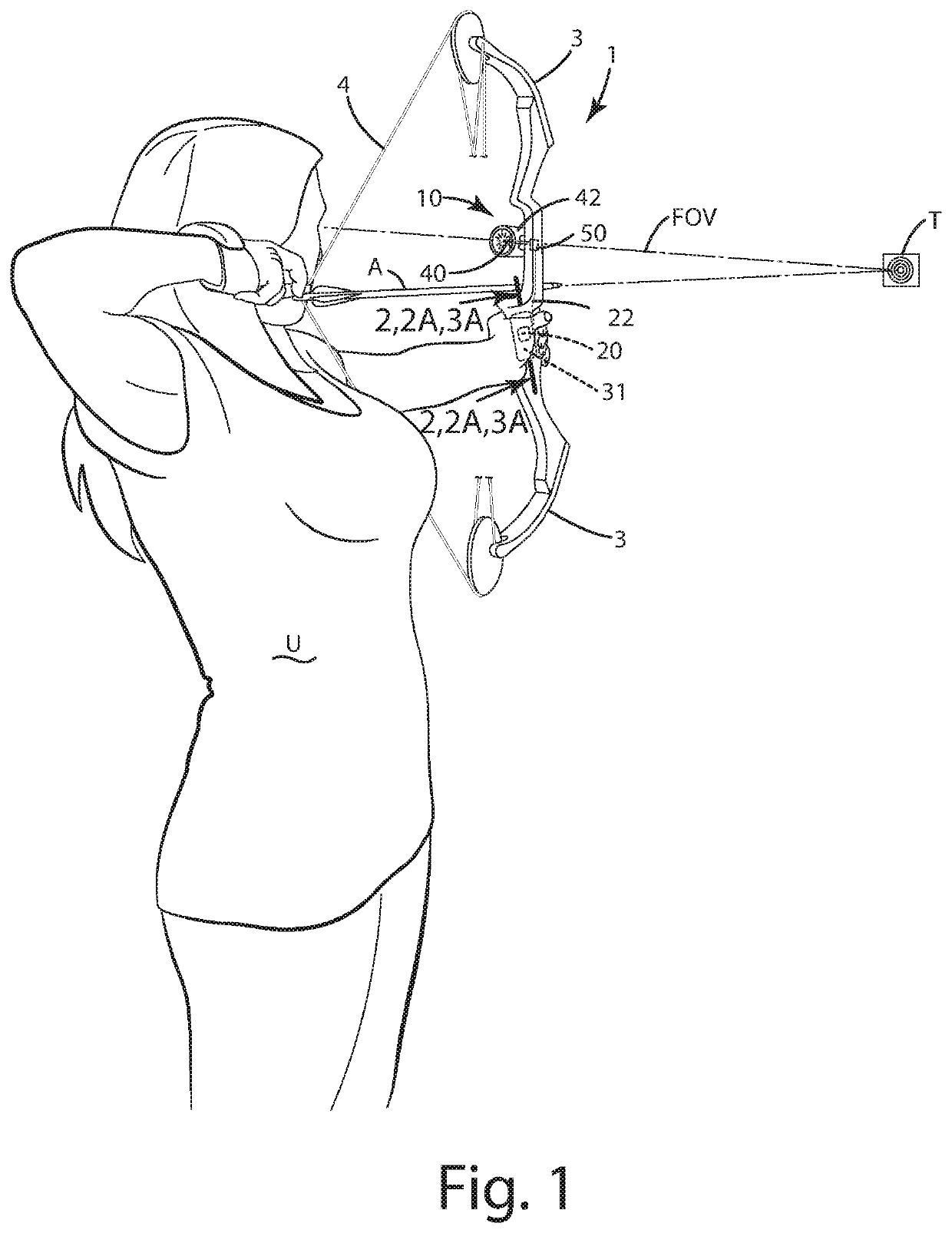
[0071]A device of a current embodiment is shown in FIGS. 1-5 and generally designated 10. The projectile shooting device 1 as illustrated in those figures is generally in the form of an archery bow, for example, a compound archery bow. It will be appreciated, however, that the aiming device of the current embodiments can be used with any type of archery bow, including but not limited to a compound bow, a recurve bow, a crossbow, or other device from which arrows or bolts can be shot. Optionally, the projectile shooting device can be in the form of a firearm, including but not limited to a handgun (for example, a pistol and / or a revolver); a rifle (for example, a long rifle, a carbine, an assault rifle, a bolt pump rifle or a battle rifle); a shotgun (of any gauge) and / or a machine gun (for example, a machine pistol, a light machine gun, a mini gun, a medium machine gun or a heavy machine gun). The firearm can include any type of action, for example, bolt action, lever action, pump a...


PUM


Abstract

A grasping element is provided including a manual actuator associated with a thermoelectric module, and an optional device powered by the thermoelectric module upon manipulation of the manual actuator. The thermoelectric module can generate electricity via a thermal gradient generated by a user's body. The electricity can power the optional device directly and / or indirectly.

Description

CROSS-REFERENCE TO RELATED APPLICATIONS[0001]This application claims benefit of U.S. Provisional Application 62 / 594,097, filed Dec. 4, 2017; and is a continuation-in-part of U.S. patent application Ser. No. 15 / 893,037, filed Apr. 18, 2018, now U.S. Pat. No. 10,302,393, which claims benefit of U.S. Provisional Application 62 / 460,131, filed Feb. 17, 2017, and of which U.S. patent application Ser. No. 15 / 893,037 also is a continuation-in-part of U.S. patent application Ser. No. 15 / 374,112, filed Dec. 9, 2016, now U.S. Pat. No. 10,094,638, which is a continuation of U.S. patent application Ser. No. 14 / 644,718, filed Mar. 11, 2015, now U.S. Pat. No. 9,528,796, which claims benefit of U.S. Provisional Application 61 / 968,069, filed Mar. 20, 2014 and U.S. Provisional Application 62 / 025,092, filed Jul. 16, 2014, which are all hereby incorporated by reference.BACKGROUND OF THE INVENTION[0002]The present invention relates to manual actuators, and more particularly to manual actuators associate...

Claims


Application Information

Patent Timeline
Patent Type & Authority Patents(United States)
IPC IPC(8): F41G1/38H01L35/32H01L35/30H01L35/18F41C23/16F41B5/14F41G1/34F41G1/467A61B5/0408
CPCF41C23/16F41G1/345H01L35/18F41B5/1403H01L35/32H01L35/30A61B5/0408F41G1/467F41G1/38H10N10/853H10N10/13H10N10/17A61B5/25
Inventor VERGARA, DAVID L.SCHULZ, CODY
Owner GRACE ENG
Why Eureka
Try Eureka