Connector system

a technology of connecting system and connector, applied in the direction of optical elements, coupling device connections, instruments, etc., can solve the problems of user errors when installing, design inflexible, damage or soiling,

Active Publication Date: 2020-05-12
REICHLE & DE-MASSARI
View PDF2 Cites 15 Cited by
  • Summary
  • Abstract
  • Description
  • Claims
  • Application Information

AI Technical Summary

Benefits of technology

[0009]In view of the above, the present invention provides a connector system that the connectors contained therein could be independently moved with respect to each other and therefore could be aligned properly with an adapter.
[0011]The present invention provides a connector system that may provide tactile feedback to a user when the connector system is locked in place.
[0012]The present invention provides a connector system that may protect the fiber ferrules contained therein from direct impact.
[0013]The present invention provides a dust protector that may protect the connectors contained therein from contamination.
[0014]In one embodiment, the connector system of the present invention includes a crimp housing and a floating block. A passage extending in a longitudinal direction is formed in the crimp housing. The floating block is disposed in the passage of the crimp housing and has an interior passage extending in the longitudinal direction for receiving a back post of a connector. The floating block may make limited three-dimensional movements with respect to the crimp housing. The connectors seated in the connector system of the present invention may be independently moved with respect to each other thereby properly aligning with an adapter.
[0015]In another embodiment, the connector system of the present invention includes a crimp housing, a floating block and a connector. A passage extending in a longitudinal direction is formed within the crimp housing. The floating block is disposed in the passage of the crimp housing and has an interior passage extending in the longitudinal direction for receiving a back post of the connector. The floating block may make limited three-dimensional movements with respect to the crimp housing. The connectors seated in the connector system of the present invention may be independently moved with respect to each other thereby properly aligning with an adapter.

Problems solved by technology

This complexity may result in user errors when installing in adverse conditions, such as outdoors or at height.
This may be difficult if the user is installing the assembly in adverse conditions, such as outdoors, at height, poor light conditions or if the user needs to reach into a narrow space.
However, this design is not robust and if the component 1304 fails, the connector holder could be pulled out place.
If the user is installing the connector in an adverse environment, he may inadvertently touch the ends of the ferrules, leading to damage or soiling.

Method used


Image

  • Connector system
  • Connector system
  • Connector system

Examples


Embodiment Construction

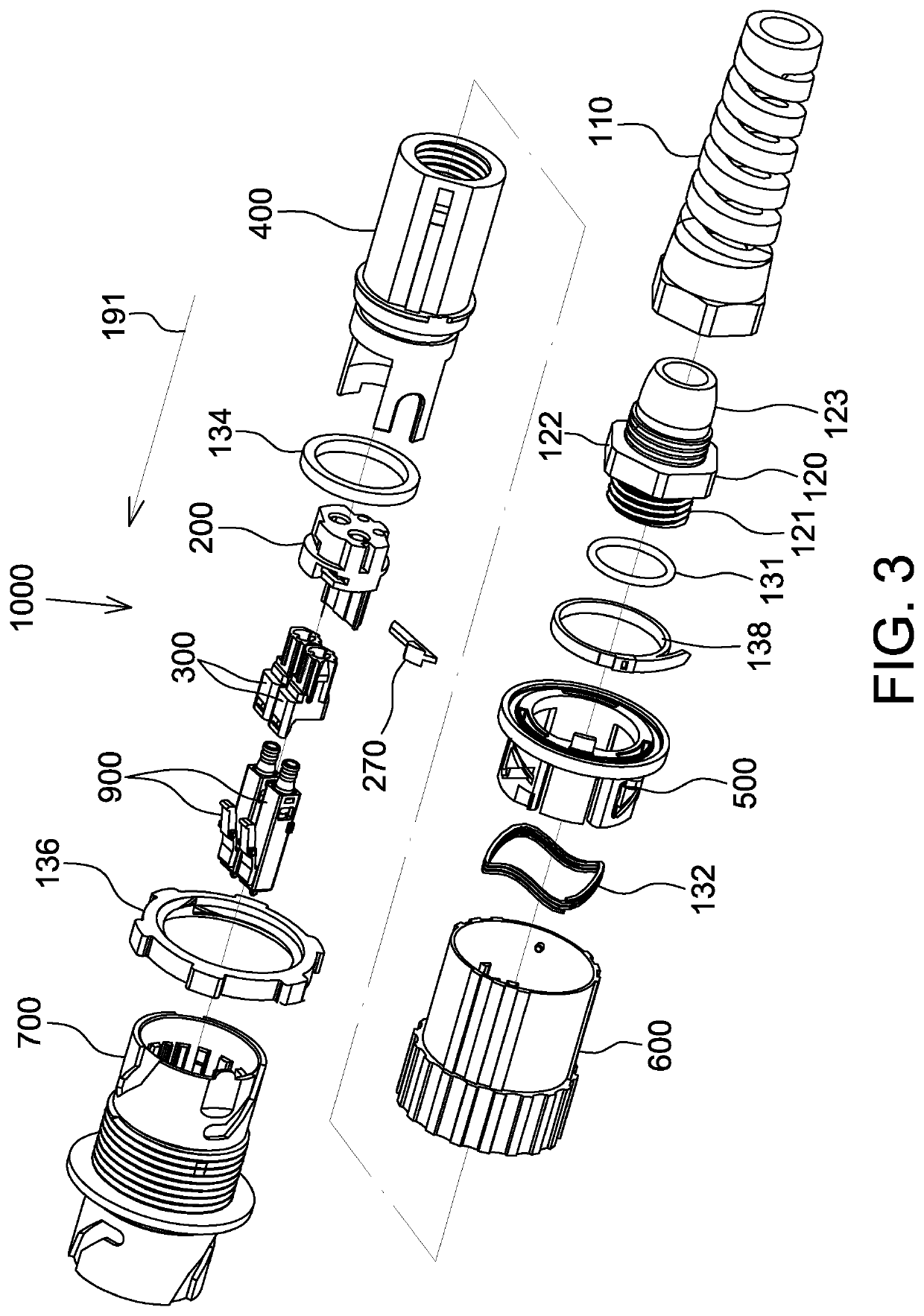
[0044]Referring to FIG. 3, which is an exploded view of the connector system 100 of the present invention. As shown in the figure, the connector system 1000 includes a boot 110, a cable gland body 120, an O-ring 131, a wave spring 132, an O-ring 134, a nut 136, a cable tie 138, a crimp housing 200, a latch 270, floating blocks 300, a stroud 400, a sliding collar 500, a plug housing 600, a receptacle 700, and connectors 900.

[0045]The boot 110 may be made from a flexible material and provide strain relief on cable (not shown) using materials and attachment techniques as are known in the art. The boot 110 has a hollow structure whose lengthwise direction is parallel to the longitudinal direction 191. The boot 110 has a hexagonal shape at its front end. The boot 110 is formed with a thread on the inner surface thereof for being screwed to the cable gland body 120.

[0046]The cable gland body 120 is hollow and has a generally cylindrical shape whose lengthwise direction is parallel to the ...


PUM


Abstract

The connector system of the present invention includes a crimp housing and a floating block. A passage extending in a longitudinal direction is formed in the crimp housing. The floating block is disposed in the passage of the crimp housing and has an interior passage extending in the longitudinal direction for receiving a back post of a connector. The floating block may make limited three-dimensional movements with respect to the crimp housing. The connectors seated in the connector system of the present invention may be independently moved with respect to each other thereby properly aligning with an adapter.

Description

RELATED APPLICATION[0001]The present application claims priority to U.S. Provisional Application Ser. No. 62 / 807,859, filed on Feb. 20, 2019, and to Chinese Patent Application Number 201910567488.9, filed on Jun. 27, 2019, the disclosures of which are hereby incorporated by reference herein in their entirety.BACKGROUND1 Technical Field[0002]This invention generally relates to a connector system, more particularly, to an optical fiber connector system.2. Description of the Related Art[0003]Recently, the use of fiber optics for communications purposes has grown immensely. Data, voice, and other communication networks are increasingly using fiber optics to carry information. An optical fiber is generally a glass fiber configured to carry light. Individual fibers may be grouped into a line capable of carrying large amounts of data simultaneously.[0004]When constructing a fiber optic network, each individual fiber is generally connected to both a source and a destination device. Addition...

Claims


Application Information

Patent Timeline
Patent Type & Authority Patents(United States)
IPC IPC(8): G02B6/38H01R24/66H01R24/20H01R13/622H01R13/64H01R13/625
CPCG02B6/3891H01R13/625H01R24/20G02B6/3879H01R24/66H01R13/622H01R13/64G02B6/3825G02B6/3817G02B6/389G02B6/3821G02B6/387G02B6/3897G02B6/3849G02B6/3894H01R13/502H01R13/5213G02B6/3869H01R13/6315
Inventor YANG, MUH-CHEN
Owner REICHLE & DE-MASSARI
Why Eureka
Try Eureka