Stator of an electric machine and production thereof

Active Publication Date: 2020-05-12
SIEMENS AG
View PDF32 Cites 2 Cited by
  • Summary
  • Abstract
  • Description
  • Claims
  • Application Information

AI Technical Summary

Benefits of technology

[0034]Casting with insulation material advantageously enables a

Problems solved by technology

The production of such a coil geometry is elaborate and time-consuming.
In particular, tight radii in the region of the winding overhang must often be insu

Method used


Image

  • Stator of an electric machine and production thereof
  • Stator of an electric machine and production thereof
  • Stator of an electric machine and production thereof

Examples


Embodiment Construction

[0057]Parts corresponding to one another are identified by the same reference characters in all the figures.

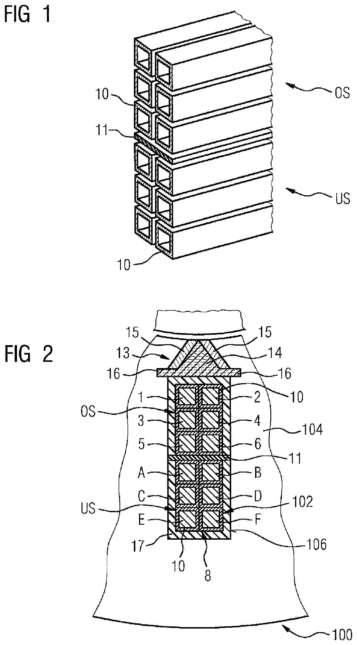
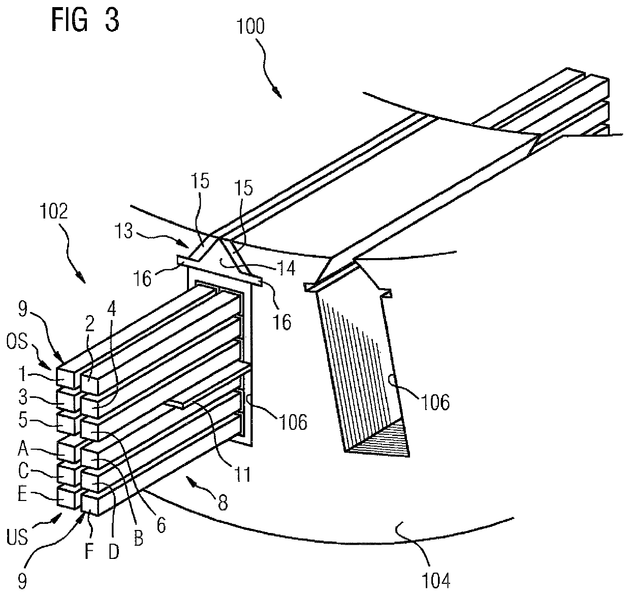
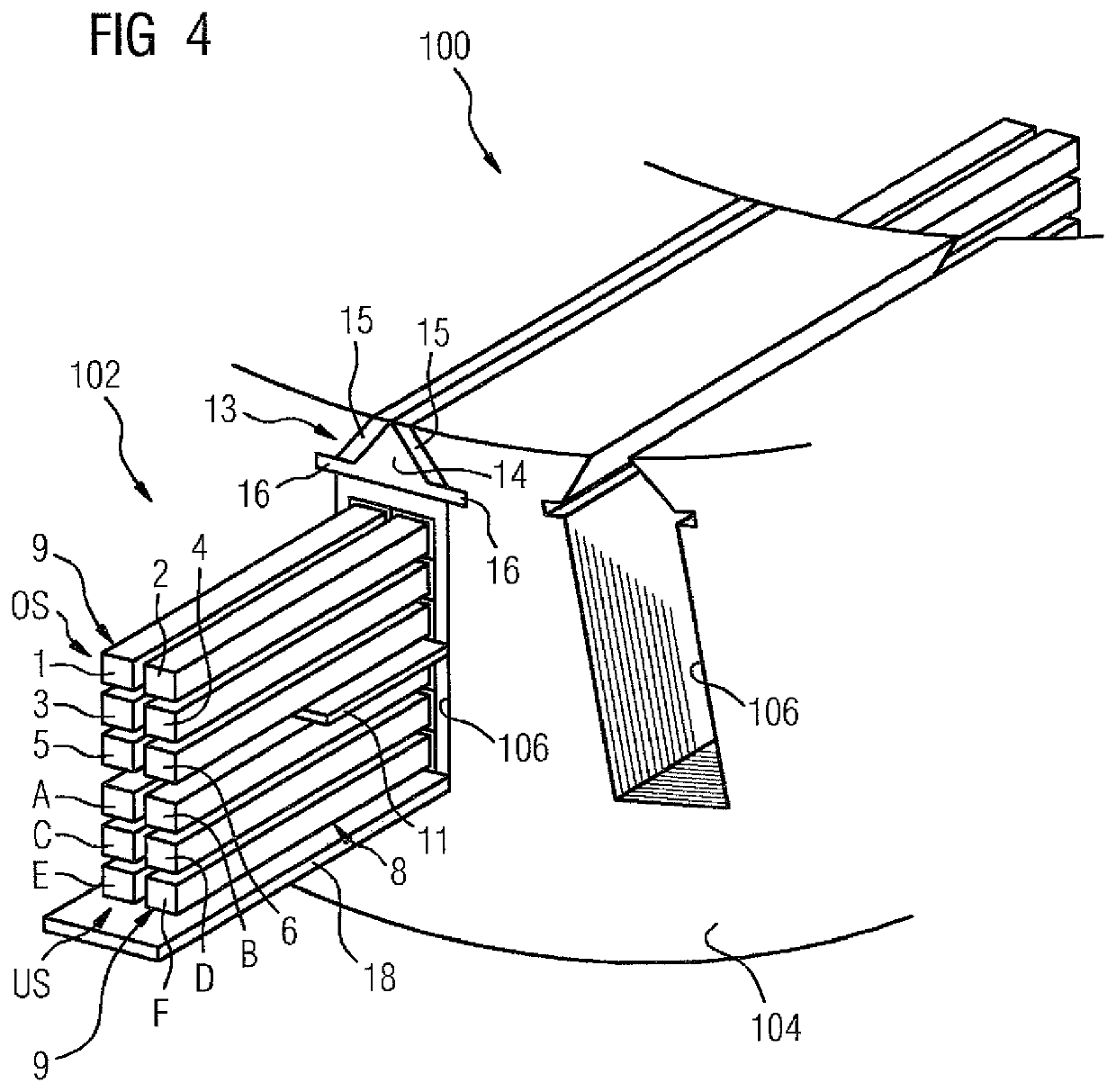
[0058]FIGS. 1 to 6 show a first exemplary embodiment of a stator 100 of a rotating electric machine and a method for the automated production of a winding 102 of the stator 100. The stator 100 comprises a laminate stack 104 having a plurality of slots 106 open towards an air gap between the stator 100 and a rotor of the electric machine. The winding 102 includes coils, the turns of which each pass through slots 106 of the laminate stack 104.

[0059]In order to produce the winding 102, in a variant of said exemplary embodiment a plurality of straight tube-like insulating hollow bodies 10 illustrated in FIG. 1 are produced initially from an electrically insulating insulation material, preferably from a ceramic material. Each of said insulating hollow bodies 10 is at least as long as a slot 106 and has a cross-section with a rectangular outer contour. The insulating hollow bodies 1...


PUM


Abstract

A stator for a rotating electric machine includes a laminate stack having a plurality of slots open towards an air gap between the stator and a rotor of the electric machine. A winding includes coils which have turns that pass through the slots of the laminate stack. The turns of the coils are electrically insulated the within the slots from each other and from the laminate stack by a ceramic material.

Description

CROSS-REFERENCES TO RELATED APPLICATIONS[0001]This application is the U.S. National Stage of International Application No. PCT / EP2015 / 056327, filed Mar. 25, 2015, which designated the United States and has been published as International Publication No. WO 20151158508 which claims the priority of European Patent Application, Serial No. 14164702.4, filed Apr. 15, 2014, pursuant to 35 U.S.C. 119(a)-(d).BACKGROUND OF THE INVENTION[0002]The invention relates to a stator of a rotating electric machine and a method for the automated production of a winding of a stator of a rotating electric machine.[0003]Rotating electric machines, in particular high-voltage asynchronous machines, consist as a general rule of a laminate stack having slots punched thereinto and a so-called distributed winding laid therein. Said winding is constructed from individual coils which exhibit a relatively complex three-dimensional geometry. The production of such a coil geometry is elaborate and time-consuming. I...

Claims


Application Information

Patent Timeline
IPC IPC(8): H02K15/09H02K3/34H02K3/50H02K3/493H02K15/00H02K15/06H02K15/10H02K3/14H02K3/38H02K1/14H02K1/16H02K3/18H02K15/02H02K3/12H02K3/30H02K15/04
CPCH02K3/30H02K1/16H02K3/493H02K15/0414H02K3/12H02K15/0018H02K15/022H02K3/345H02K1/146H02K15/105H02K3/18H02K15/062H02K3/34H02K3/14H02K15/0081H02K3/38H02K15/085H02K1/04
Inventor SCHERER, MATTHIASDEEG, CHRISTIANEICHINGER, BENJAMINJOSEPH, ERICSCHARF, UWESTEGHERR, MICHAELWEISS, SEBASTIAN
Owner SIEMENS AG
Why Eureka
Try Eureka