Internal combustion engine

a combustion engine and combustion chamber technology, applied in the direction of machines/engines, electrical control, exhaust treatment electric control, etc., can solve the problem of intentionally caused exhaust scavenging, and achieve the effect of suppressing the deterioration of exhaust emission

Active Publication Date: 2020-05-19
TOYOTA JIDOSHA KK
View PDF12 Cites 1 Cited by
  • Summary
  • Abstract
  • Description
  • Claims
  • Application Information

AI Technical Summary

Benefits of technology

[0016]According to the present invention, there is provided an internal combustion engine which can suppress the deterioration of exhaust emission immediately after scavenging.

Problems solved by technology

For example, in an internal combustion engine provided with a supercharger such as a turbocharger, scavenging is intentionally caused if the amount of intake air is insufficient for the requested torque.

Method used


Image

  • Internal combustion engine
  • Internal combustion engine
  • Internal combustion engine

Examples


first embodiment

[0030]First, referring to FIG. 1 to FIG. 8, a first embodiment of the present invention will be explained.

[0031]

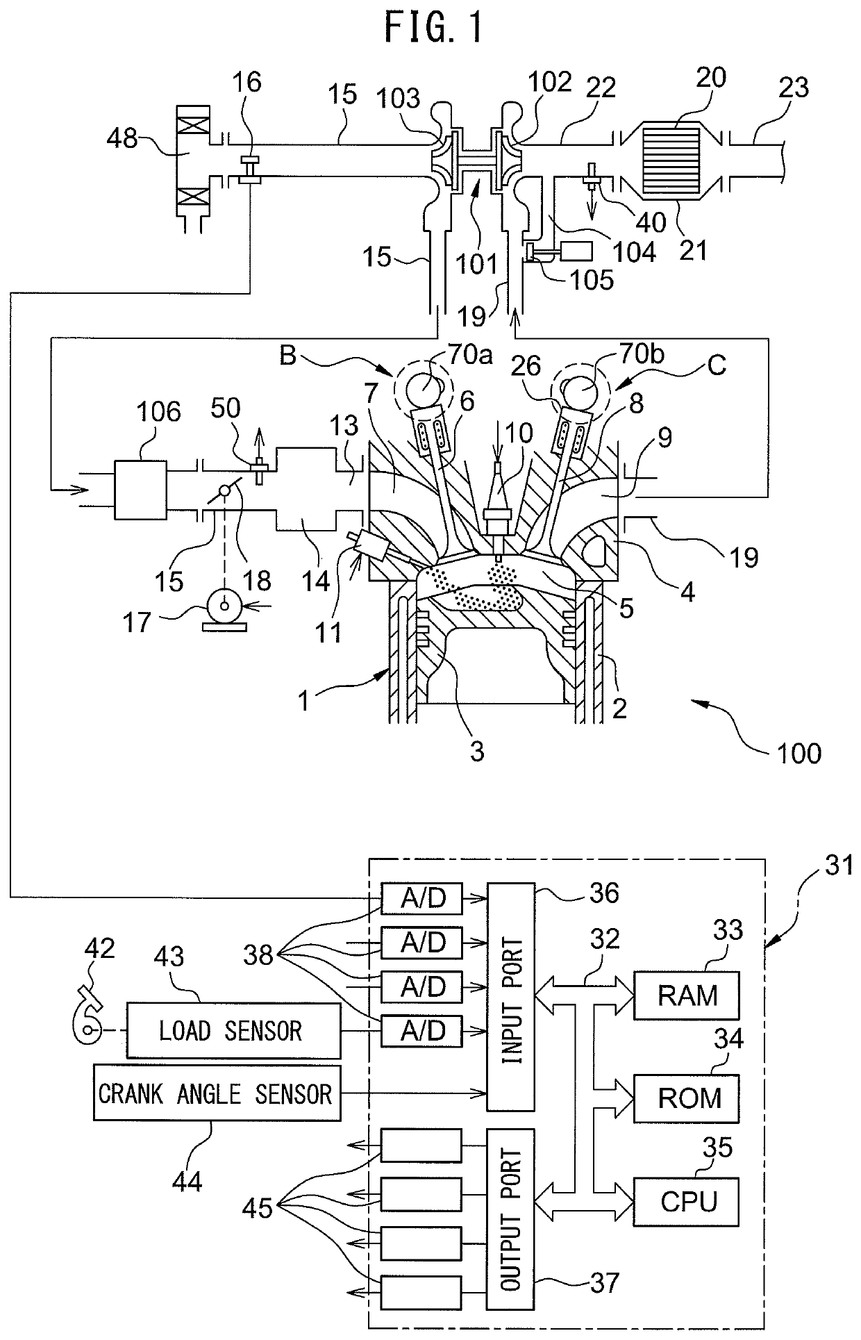
[0032]FIG. 1 is a schematic view of an internal combustion engine 100 in an embodiment of the present invention. The internal combustion engine 100 is provided with an engine body 1 including a cylinder block 2 and a cylinder head 4. In the present embodiment, the internal combustion engine 100 is a spark ignition type internal combustion engine. Note that, the internal combustion engine 100 may also be a compression ignition type internal combustion engine (diesel engine). Inside of the cylinder block 2, piston 3 is arranged to reciprocate inside the cylinder block 2.

[0033]A combustion chamber 5 is formed between the piston 3 and the cylinder head 4. The cylinder head 4 is formed with intake ports 7 and exhaust ports 9. The intake ports 7 and exhaust ports 9 are connected to the combustion chambers 5. An intake valve 6 is arranged at an end part of each intake port 7 and ...

second embodiment

[0095]Next, referring to FIG. 9 and FIG. 10, a second embodiment of the present invention will be explained. Note that the configuration and control of the internal combustion engine of the second embodiment are basically the same as the internal combustion engine of the first embodiment, so in the following explanation, mainly parts differing from the first embodiment will be explained.

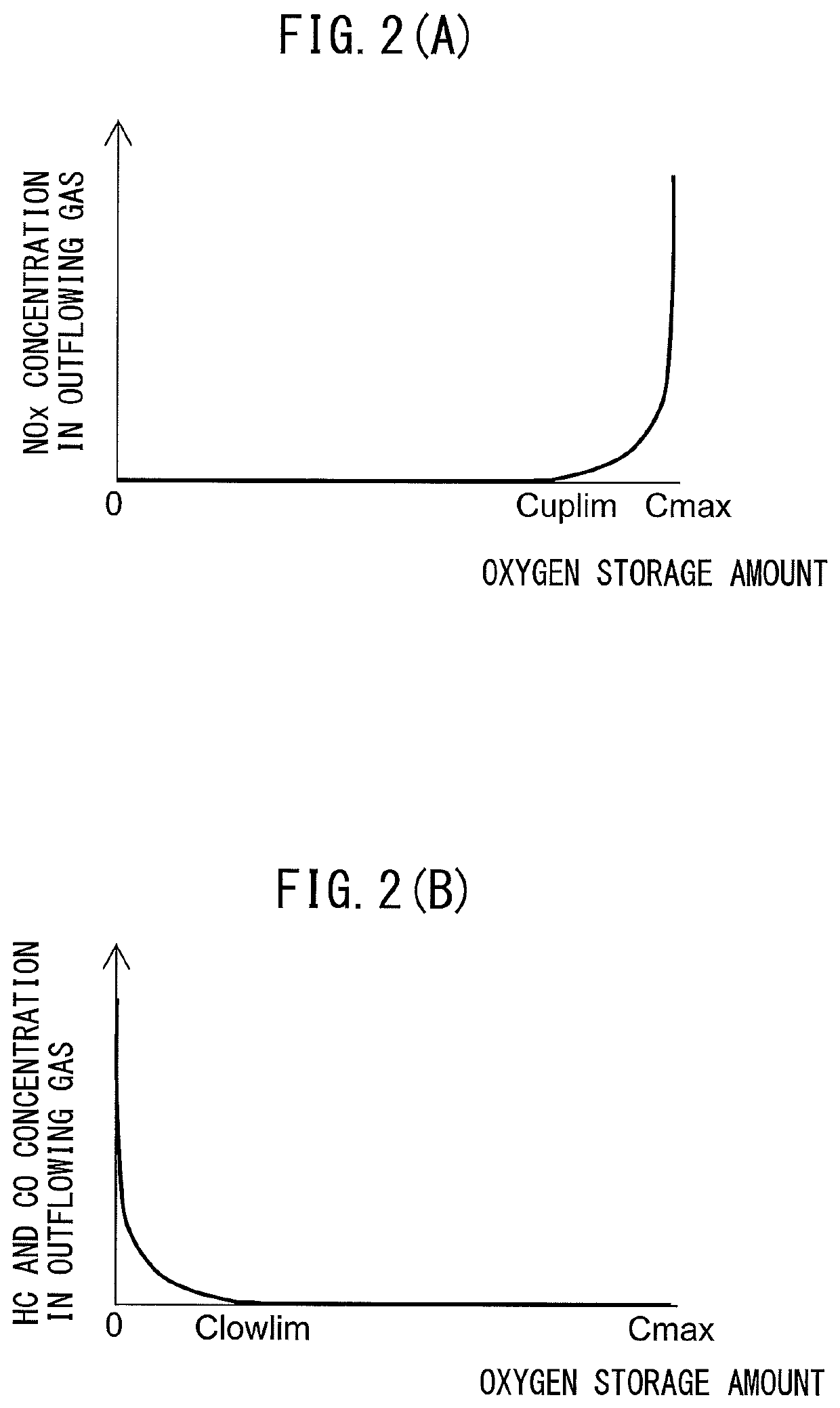
[0096]If the fuel supplied to the exhaust passage at the initial cycle after scavenging is small, the amount of oxygen released from the exhaust purification catalyst 20 due to the supplied fuel becomes smaller, so it is not possible to effectively suppress a rapid increase in oxygen storage amount of the exhaust purification catalyst 20 due to the expulsion of air. On the other hand, if a large amount of fuel is supplied to the exhaust passage at the initial cycle after scavenging, the exhaust purification catalyst 20 rapidly decreases in oxygen storage amount, so unburned gas is liable to flow out ...


PUM


Abstract

The internal combustion engine comprising: a catalyst arranged in an exhaust passage and able to store oxygen, a variable valve timing mechanism able to change a valve overlap amount between an intake valve and an exhaust valve, and a fuel supplying means for feeding fuel to the exhaust passage. The fuel supplying means feeds fuel to the exhaust passage only in an initial cycle after scavenging where valve overlap causes air to be expelled from an intake passage through a cylinder to the exhaust passage if such scavenging occurs.

Description

CROSS-REFERENCE TO RELATED APPLICATION[0001]The present application claims priority to Japanese Patent Application No. 2015-115943 filed on Jun. 8, 2015, which is incorporated herein by reference in its entirety.TECHNICAL FIELD[0002]The present invention relates to an internal combustion engine.BACKGROUND ART[0003]In an internal combustion engine, if generating valve overlap between intake valve and exhaust valve when the pressure inside an intake port is higher than the pressure inside an exhaust port, air is blown from the intake passage through the cylinder to the exhaust passage in what is known as “scavenging”. For example, in an internal combustion engine provided with a supercharger such as a turbocharger, scavenging is intentionally caused if the amount of intake air is insufficient for the requested torque. By causing scavenging, the amount of exhaust gas increases and the speed of the turbine of the supercharger is raised. As a result, the pressure of the intake air is rai...

Claims


Application Information

Patent Timeline
Patent Type & Authority Patents(United States)
IPC IPC(8): F02D13/02F01N3/10F02B25/14F02D41/00F02D41/02F02D41/40F01N3/08F01N9/00F02B75/12F02B23/10F02D41/38F01N3/20
CPCF02D41/0235F02D41/405F02B25/145F01N9/00F01N3/101F02D41/0007F01N3/0814F02D13/0261Y02T10/44F02B2075/125Y02T10/22Y02T10/144Y02T10/47F01N3/2033F02B23/104F01N2900/08F02D2041/389F02D2041/001Y02T10/123F01N2560/025Y02T10/18Y02T10/12Y02T10/40
Inventor KIMURA, KOICHIOKUBO, TAKUYANAKAGAWA, NORIHISA
Owner TOYOTA JIDOSHA KK
Why Eureka
Try Eureka