Light fixture assembly having a heat conductive cover with sufficiently large surface area for improved heat dissipation

a technology of heat conductive cover and light fixture, which is applied in the direction of light source, lighting device details, lighting and heating apparatus, etc., can solve the problems of reducing the operable life of many reducing reliability and operational life, and reducing the efficiency of led based illumination assemblies. , to achieve the effect of facilitating heat transfer, facilitating efficient dissipation of an adequate amount of heat, and avoiding excessive heat build-up

Active Publication Date: 2020-05-19
SILESCENT LIGHTING
View PDF175 Cites 0 Cited by
  • Summary
  • Abstract
  • Description
  • Claims
  • Application Information

AI Technical Summary

Benefits of technology

[0018]In at least one preferred embodiment of the present invention, the cover structure has a larger transverse and substantially overall dimension than that of the mounting assembly in order to provide structural and decorative versatility to the formation of the light fixture assembly. In addition, the larger dimensioning as well as the cooperative configuring of the cover assembly further facilitates an efficient dissipation of an adequate amount of heat from the LED array of the illumination assembly, such that the illumination assembly may be operated under optimal conditions without excessive heat build-up.
[0019]In order to further facilitate the transfer of heat to the surrounding environment, correspondingly disposed surfaces of the mounting assembly and the cover structure may be disposed in continuous confronting engagement with one another over substantially all or at least a majority of the corresponding surface area of the mounting assembly, including by having all or part thereof being integrally formed with one another. Regardless, a substantial portion of the cover structure is disposed substantially exposed to the area being illuminated by the illumination assembly, the enlarged exterior surface area thus able to dissipate heat via radiation from the illumination assembly. For example, in the case of a recess mounted light fixture, rather than having to rely solely on conductivity via a large cumbersome, contained heat sink, the cover structure is able to utilize all of its exposed surface area to radiate heat, as it is not trapped behind the fixture in a wall surface, and an increase in heat dissipation is achievable by increasing the surface area of the cover structure and therefore the amount of radiation that can be achieved. Moreover, although not required for effective radiation of heat, by being exterior of the mounting structure and / or at least exposed to the area being illuminated, the cover structure and therefore the heat sink, has more access to air movement which can also help to dissipate heat from the fixture.
[0020]In an additional embodiment of the present invention the cover structure and light shield, or at least the function thereof, may be integrated into a single piece and further disposed in light reflecting relation to the illumination assembly. Thus, the invention can better direct light while maintaining the heat radiating / dissipating characteristic of the above embodiments. Such an embodiment may comprise, for example, a bowl or dish-shaped cover structure with a light shield comprising an at least partially reflective surface of the interior of the cover structure. The cover structure can be broadly described as having a closed end with mounting assembly disposed thereon, and an open end at least partially defined by an annular step disposed thereabout.
[0021]In this embodiment, the cover structure retains its enlarged exterior surface area and, being disposed in heat conducting relation to the mounting assembly, retains its ability to conduct heat to the enlarged exterior surface area and radiate heat therefrom into the environment to be illuminated. Furthermore, the addition of an annular step to an open end of the embodiment further enhances the radiative characteristics such that the cover structure could be disposed behind a mounting surface, leaving substantially only the annular step disposed in communication with the environment to be illuminated.
[0022]Other components of this embodiment, such as the mounting structure and illumination assembly, can retain essentially the same structural features and / or functional operation as the above embodiments and thus may not need to be modified.

Problems solved by technology

However, certain disadvantages and problems associated with the use of LED based illumination assemblies are commonly recognized.
As such, LED illumination assemblies tend to generate a significant amount of heat during their operation, which in turn may derogatorily affect the light generated by the LED array as well as reduce the reliability and operational life thereof.
Accordingly, the operable life of many LED based illumination assemblies may be significantly reduced due to premature failure of one or more light emitting diodes associated with a light fixture or other device, and / or the maximization of power and illuminating output for such an illumination assembly is limited.
However, many known attempts do not effectively accomplish optimal heat transfer, resulting in lower operational performance and a reduced operational life as generally set forth above.
Moreover, there is especially a need as it relates to recessed or flush lighting wherein traditional heat dissipating structures are hampered by being contained within a wall or other mounting surface.
Specifically, known recessed or flush mounting structure typically include large unattractive heat sinks contained within the mounting surface and / or otherwise concealed.
Even then, however, there are limitations on the power and illumination ability of the light source, as there are usually space and weight constraints for the recessed heat sink, especially in the context of a retrofit wherein the cavity into which the light source will be positioned has been predefined based upon conventional incandescent lighting specifications.

Method used


Image

  • Light fixture assembly having a heat conductive cover with sufficiently large surface area for improved heat dissipation
  • Light fixture assembly having a heat conductive cover with sufficiently large surface area for improved heat dissipation
  • Light fixture assembly having a heat conductive cover with sufficiently large surface area for improved heat dissipation

Examples


Embodiment Construction

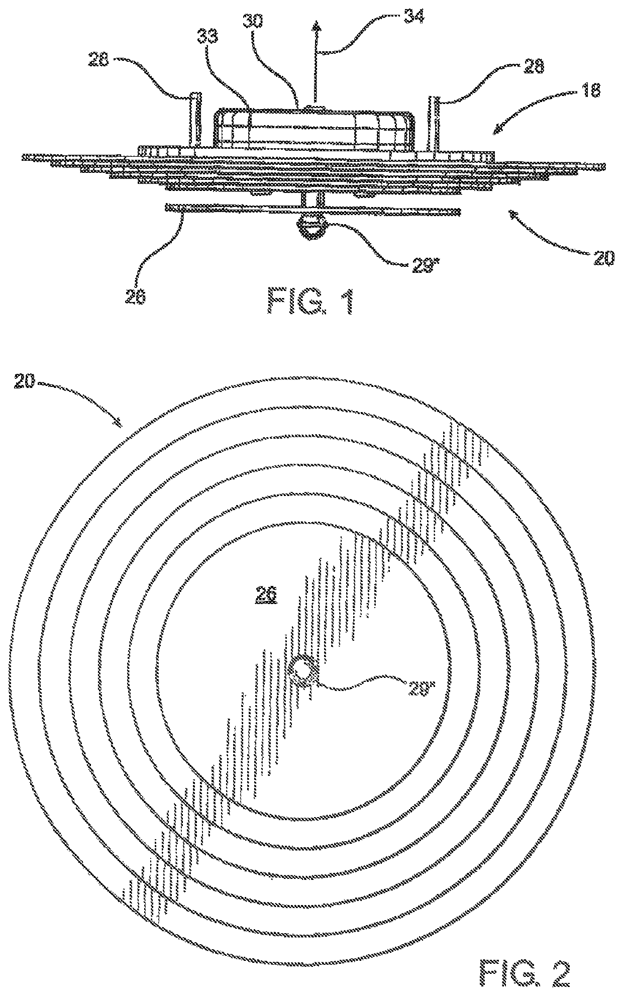
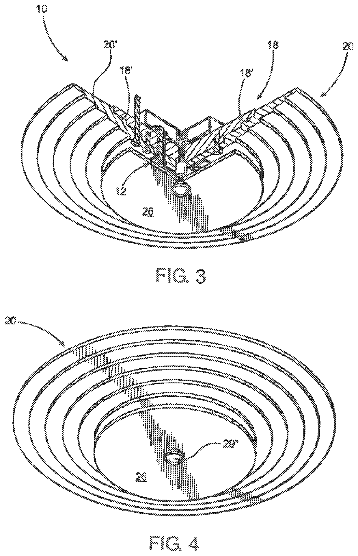
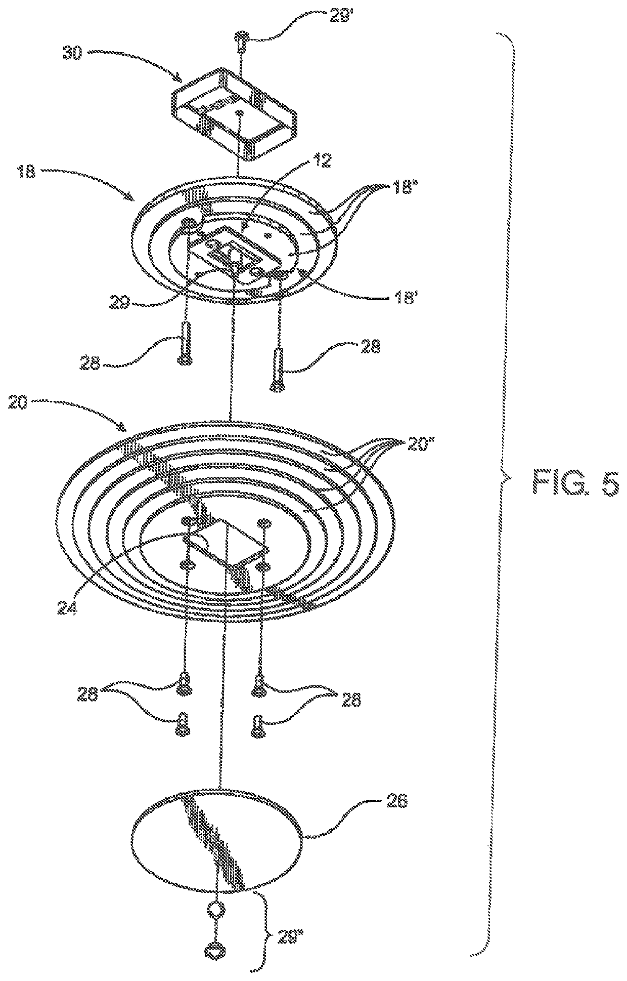
[0041]As shown in the accompanying drawings, the present invention is directed to a light fixture generally indicated as 10. The light fixture 10 is of the type which may be installed in any of a variety of commercial, domestic or other sites and is decorative as well as functional to effectively illuminate a given area or space in the vicinity of the installed location. More specifically, and with reference primarily to FIGS. 1 through 6, the light fixture assembly 10 includes an illumination assembly generally indicated as 12 comprising one or more light emitting diodes 14 connected to electrical control circuitry 16. The control circuitry 16 is preferably in the form of a printed circuit structure 16′ or printed circuit board having the various electrical or circuitry components integrated therein.

[0042]In addition, the light fixture assembly 10 includes a mounting assembly generally indicated as 18 and preferably, but not necessarily, comprising a plate or disk like configuratio...


PUM

PropertyMeasurementUnit
surface areaaaaaaaaaaa

Abstract

A light fixture assembly including an illumination assembly in the form of one or more light emitting diodes is interconnected to an electrical energy source by control circuitry. A mounting assembly supports the illumination assembly and a cover structure is disposed in heat transferring relation to the illumination assembly, wherein the cover structure, which has an enlarged surface area formed of a heat conductive material, defines a decorative exterior of the light fixture and is disposed exterior of a mounting surface, thereby effectively dissipating the heat generated by the LED illumination assembly towards the environment being illuminated by the light fixture.

Description

CLAIM OF PRIORITY[0001]The present application is a continuation-in-part application of U.S. patent application Ser. No. 15 / 097,008 filed on Apr. 12, 2016, which is a continuation-in-part application of U.S. patent application Ser. No. 14 / 445,172 filed on Jul. 29, 2014, which is a continuation-in-part application of U.S. patent application Ser. No. 13 / 749,156 filed on Jan. 24, 2013, which is matured into U.S. Pat. No. 8,789,980 on Jul. 29, 2014, which is a continuation-in-part of U.S. patent application Ser. No. 12 / 902,852 filed on Oct. 12, 2010, which is matured into U.S. Pat. No. 8,360,614 on Jan. 29, 2013, which is a continuation-in-part of U.S. patent application Ser. No. 12 / 215,047 filed on Jun. 24, 2008, which matured into U.S. Pat. No. 7,810,960 on Oct. 12, 2010, which is a continuation-in-part of U.S. patent application Ser. No. 11 / 985,056, filed on Nov. 13, 2007, which matured in U.S. Pat. No. 7,980,736 on Jul. 19, 2011.[0002]Additionally, U.S. patent application Ser. No. 1...

Claims


Application Information

Patent Timeline
Patent Type & Authority Patents(United States)
IPC IPC(8): F21V29/70F21V3/02F21Y115/10
CPCF21V3/02F21V29/70F21Y2115/10F21S8/04
Inventor SODERMAN, DARYLSUTHERLAND, MARK
Owner SILESCENT LIGHTING
Why Eureka
Try Eureka