
Suture anchor and method for attaching soft tissue to bone

a technology of soft tissue and bone, which is applied in the field of suture anchors and methods for attaching soft tissue to bone, can solve the problems of affecting the application of sutures, affecting the healing effect of soft tissue,

Active Publication Date: 2020-05-26
VYHMEISTER EDWIN D
View PDF6 Cites 1 Cited by
  • Summary
  • Abstract
  • Description
  • Claims
  • Application Information

AI Technical Summary

Benefits of technology

The anchor provides strong, cost-effective, and quick fixation of sutures to bone without damaging the bone or requiring extra holes, suitable for both small and large bones, with enhanced holding power due to its design and materials, reducing surgical time and costs.

Problems solved by technology

This design has the disadvantage of potential trauma and damage to the bone and surrounding tissues.
This type also has the possibility that it could come loose and it has limited applications due to the increased access that is required to apply the impacting forces to fix the anchor to the bone.
Another disadvantage of this type of anchor is that it is only suited to larger bone because sometimes smaller bone and surrounding or attached tissues cannot handle the impact forces required to set this type of anchor into place.
The hammered in type of anchor is also associated with high costs and increased difficulty removing them in the future if the need arises.
Other disadvantages of this type of anchor is that special tools are also required to set them in place, they are time consuming to install and they require a larger hole or bone tunnel to be used which can weaken the bone.
The screw insertion method has disadvantages because it tends to be time consuming, very costly and typically requires specialized high priced tools to use.
Another disadvantage of the screw in anchor is that many screw in designs require the bone tunnel hole to be larger and tapped to receive the screw in anchor.
The larger hole, the tapping and or insertion of the screw can weaken the bone and cause additional damages to surrounding tissues and take more time to install.
The screw in anchor design also has the disadvantage of being very high priced as compared to some other suture anchor designs.
Drilling extra holes to accommodate the anchor or tools to install the anchor are disadvantages because the extra hole can weaken the bone and the installation process takes longer and is more complicated plus this style can have limited applications because of the need of the extra hole.
Many prior art anchors require special tools during the surgical installation procedure and without the specially designed installation tool the associated anchor could not be used or installed.
These required tools have the disadvantage of being very expensive, intricate and highly specialized to one single task of inserting suture anchors only.
Other prior art of suture anchors include designs made of twisted wire but their engineering has strength disadvantaged due to their inherent design.
None of the prior art showing anchors made from twisted wire are designed with legs that are straight by design.
Although the prior art twisted wire designs can solve the problems of cost and simplicity associated with most other anchor designs, because the wire legs are bent they inherently offer less resistance to further bending than wires that are straight.
Prior art using twisted wire to fabricate a suture anchor has the disadvantage of the anchor pulling free from the bone tunnel because the legs bend easier and release their grip on the bone tunnel walls.
Additionally, all prior art using bent wires have the disadvantage of the supporting legs on the same plane which also weakens the anchors holding ability as well.
Additionally, most of the foregoing exemplar prior art suture anchors suffer from the disadvantage of requiring special tools to insert and or deploy the anchor into the bone tunnel.
These special tools add to the already high costs of suture anchors plus they complicate the insertion process and add time to the surgical procedure adding further to the high costs of using suture anchors for any surgery.

Method used


Image

  • Suture anchor and method for attaching soft tissue to bone
  • Suture anchor and method for attaching soft tissue to bone

Examples


Embodiment Construction

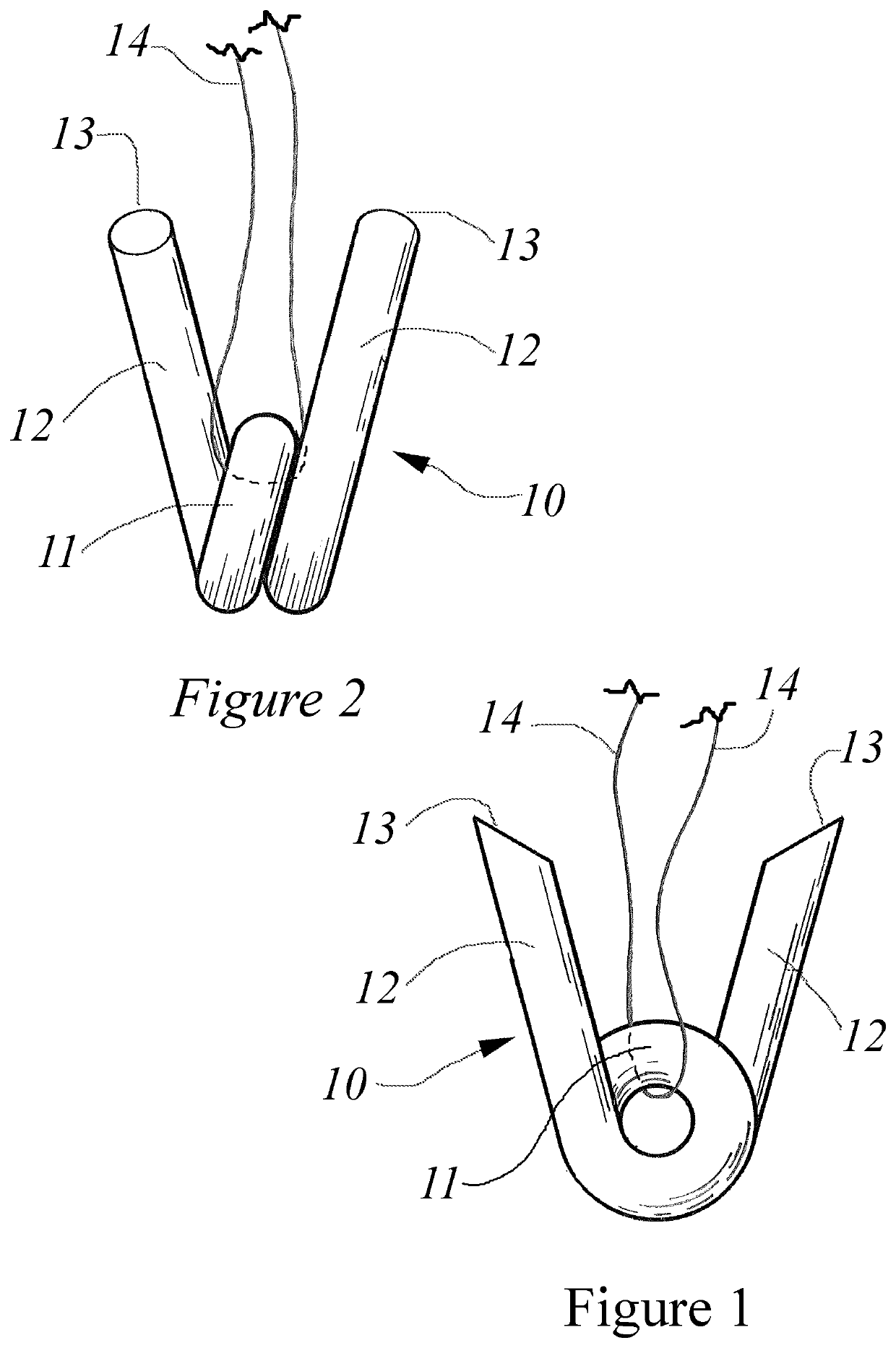
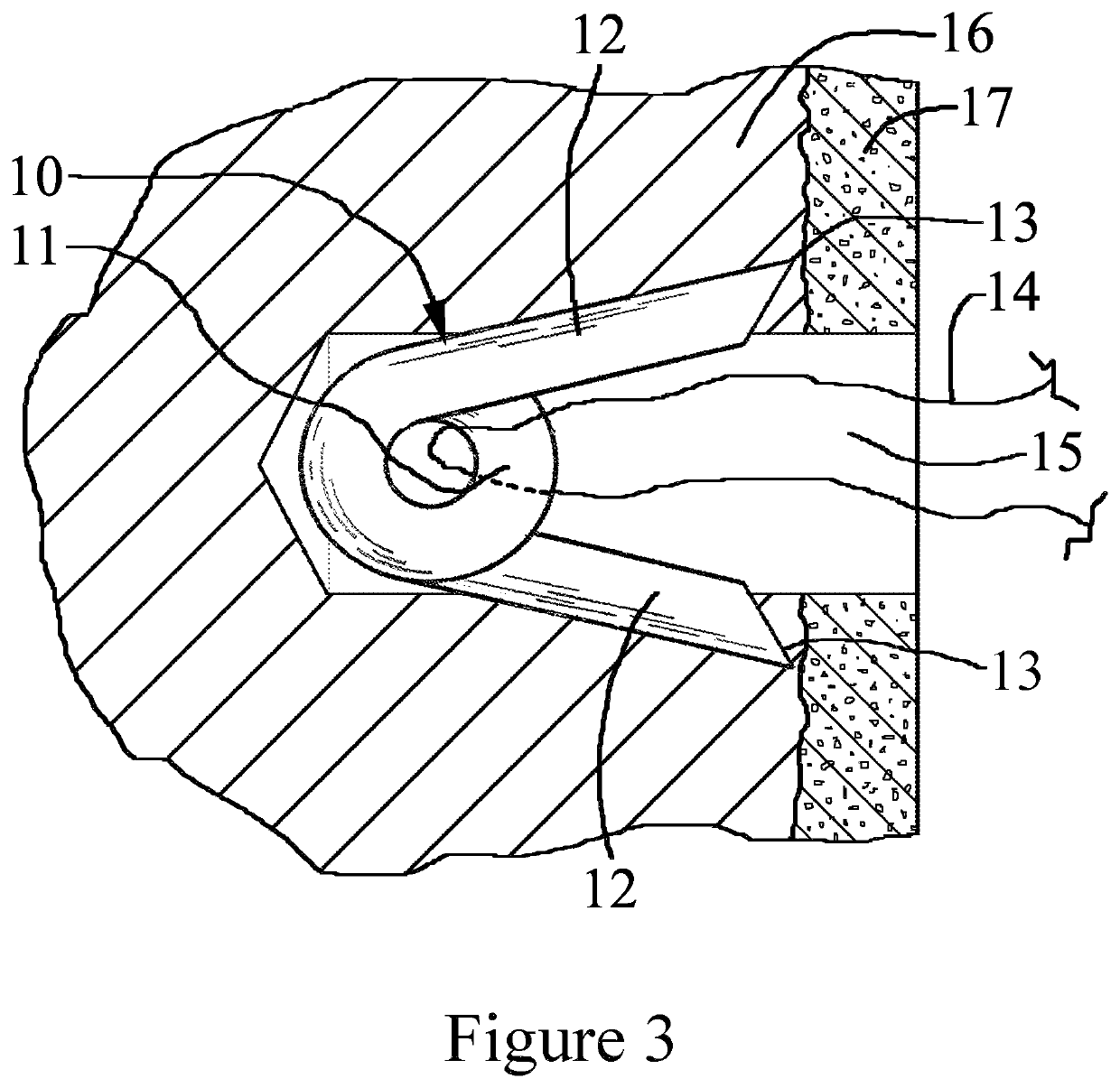
[0025]Referring specifically to FIGS. 1, 2 and 3, a resiliently flexible wire is bent and twisted to form a suture anchor 10 with a suture retaining loop 11 positioned at the center of a precisely measured and cut length of wire. The suture loop 11 constitutes the proximal end of the anchor device 10 and in the preferred embodiment has a helical shape that provides spring flexibility to the two wire ends that make up the two diverging legs 12. In the illustrated embodiment the wire forms approximately one and three quarters helical loops 11 with the ends of the wire extending away from the loop to make two legs 12 diverging at a desired angle of between 30 degrees to 45 degrees depending on the anchors intended use. The two legs 12, when unconstrained, have their pointed ends 13 spaced at a distance that is greater than the diameter of the bone tunnel 15 that has been drilled into the bone 16 to which the suture anchor is to be deployed. The suture 14 is passed through the suture re...


PUM


Abstract

A suture anchor made of a single length of wire that forms a suture retaining loop having two diverging legs, each having a pointed end. The transverse spacing of the diverging legs is greater than the diameter of the bone tunnel. The suture anchor may be spring loaded and set into the bone tunnel so that the distal points of each diverging leg are below the surface of a bone cortex, the sharp distal points of each diverging leg expand out laterally under pressure and penetrate the bone tunnel wall prohibiting removal of the suture anchor. The diverging legs further penetrate the bone tunnel wall in response to applied withdrawal forces.

Description

REFERENCE TO RELATED APPLICATIONS[0001]This application claims the priority of provisional application Ser. No. 61 / 622,822 filed Apr. 11, 2012; the disclosures of which is incorporated herein by reference.BACKGROUND OF THE INVENTION1. Technical Field[0002]This invention pertains to the methods and apparatus utilized in surgical procedures involving the fixation of soft tissue to bone tissue and in particular to a novel method and apparatus for anchoring sutures to bone.2. Discussion of the Prior Art[0003]As a common procedure of various surgeries, open, arthroscopic or endoscopic, it is necessary to attach a suture to bone tissue. For example, in certain procedures requiring the suturing of soft tissue such as muscle, ligaments or tendons to bone tissue the suture must be attached to bone in order for the soft tissue to be sutured to the bone. Prior art includes numerous suture anchors in various sizes, types and methods which can be adapted to be secured to pre-drilled holes or tun...

Claims


Application Information

Patent Timeline
Patent Type & Authority Patents(United States)
IPC IPC(8): A61B17/04
CPCA61B17/0401A61B2017/0437A61B2017/0414
Inventor VYHMEISTER, EDWIN D.JENSEN, JEFF A.
Owner VYHMEISTER EDWIN D
Learn More