
Plasma processing apparatus

a processing apparatus and plasma technology, applied in plasma techniques, electrical apparatus, electric discharge tubes, etc., can solve the problems of long maintenance time, heavy burden on workers, and inability to achieve the effect of reducing maintenance time and improving processing efficiency

Active Publication Date: 2020-05-26
HITACHI HIGH-TECH CORP
View PDF10 Cites 0 Cited by
  • Summary
  • Abstract
  • Description
  • Claims
  • Application Information

AI Technical Summary

Benefits of technology

The present invention provides a vacuum processing apparatus with improved processing efficiency and ease of maintenance. Specifically, the apparatus has a unique structure where a processing chamber is provided in the innermost container, while other containers are nested inside. The inner container needs to be enclosed in the vacuum container to separate the inside and outside in an airtight manner. To take out the inner container, workers need to carry and move the heavy inner container from the inside of the vacuum container, which causes long maintenance time and decreases processing efficiency. Additionally, the diameter of the vacuum container becomes larger as the diameter of the wafer in processing increases, which further increases the footprint of the apparatus on the floor of a building. The present invention solves these issues and provides a vacuum processing device with improved efficiency in processing and maintenance.

Problems solved by technology

The foregoing conventional techniques have problems due to insufficient considerations in the following respects.
However, the nested structure of the inner and outer containers puts a heavy burden on a worker at the time of removal of the inner container.
This causes a long maintenance time and places a heavy burden on the worker.
In addition, the downtime of the apparatus becomes longer, thereby deteriorating the processing efficiency of the apparatus.
Further, as the diameter of the wafer to be processed is larger, the diameter of the vacuum container outside the inner container storing the wafer inevitably becomes larger.
This brings about further increase in the footprint of the apparatus processing the wafer on the floor of a building.

Method used


Image

  • Plasma processing apparatus
  • Plasma processing apparatus
  • Plasma processing apparatus

Examples


Embodiment Construction

[0034]An embodiment of the present invention will be described with reference to the drawings.

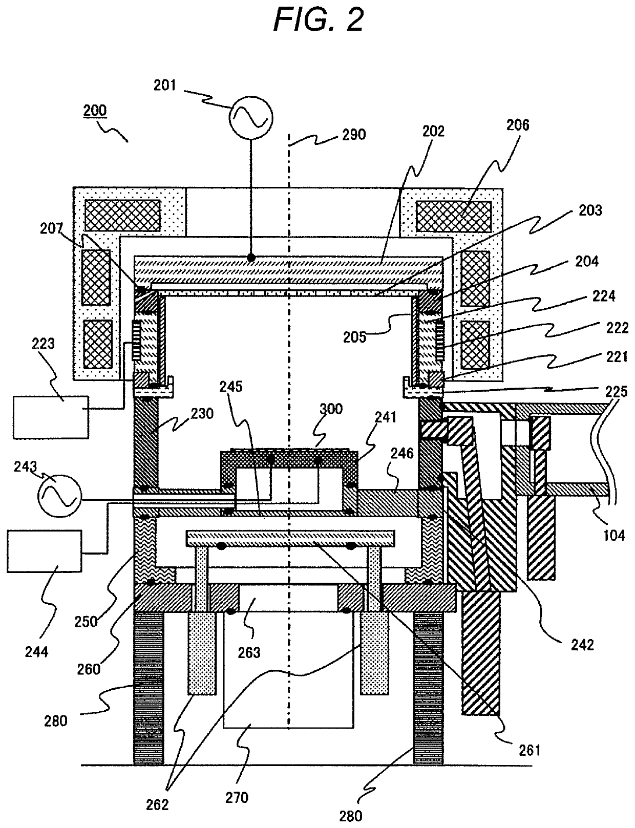
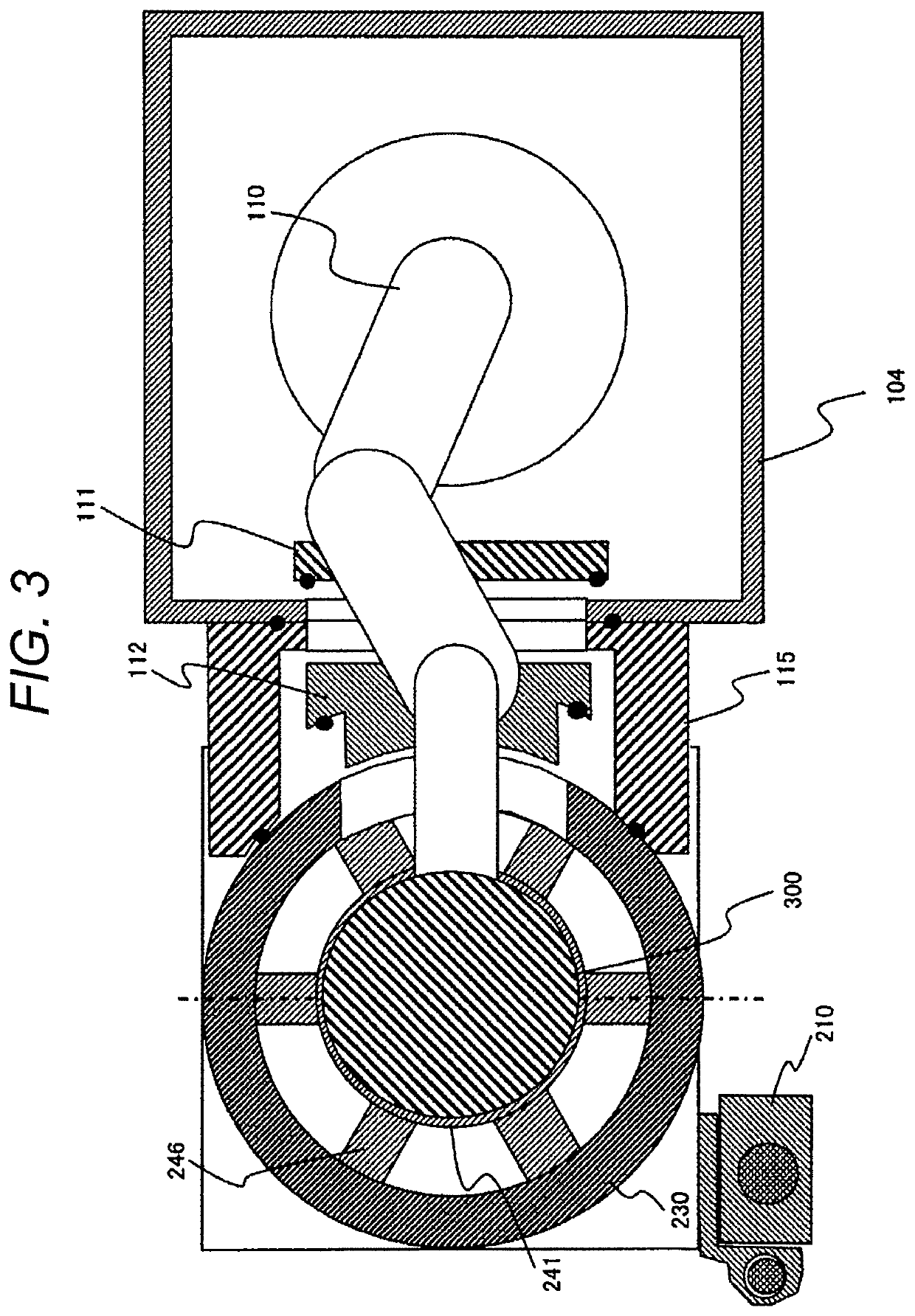
[0035]An example of the present invention will be described with reference to FIGS. 1 to 14. Identical reference signs in the drawings indicate identical components.

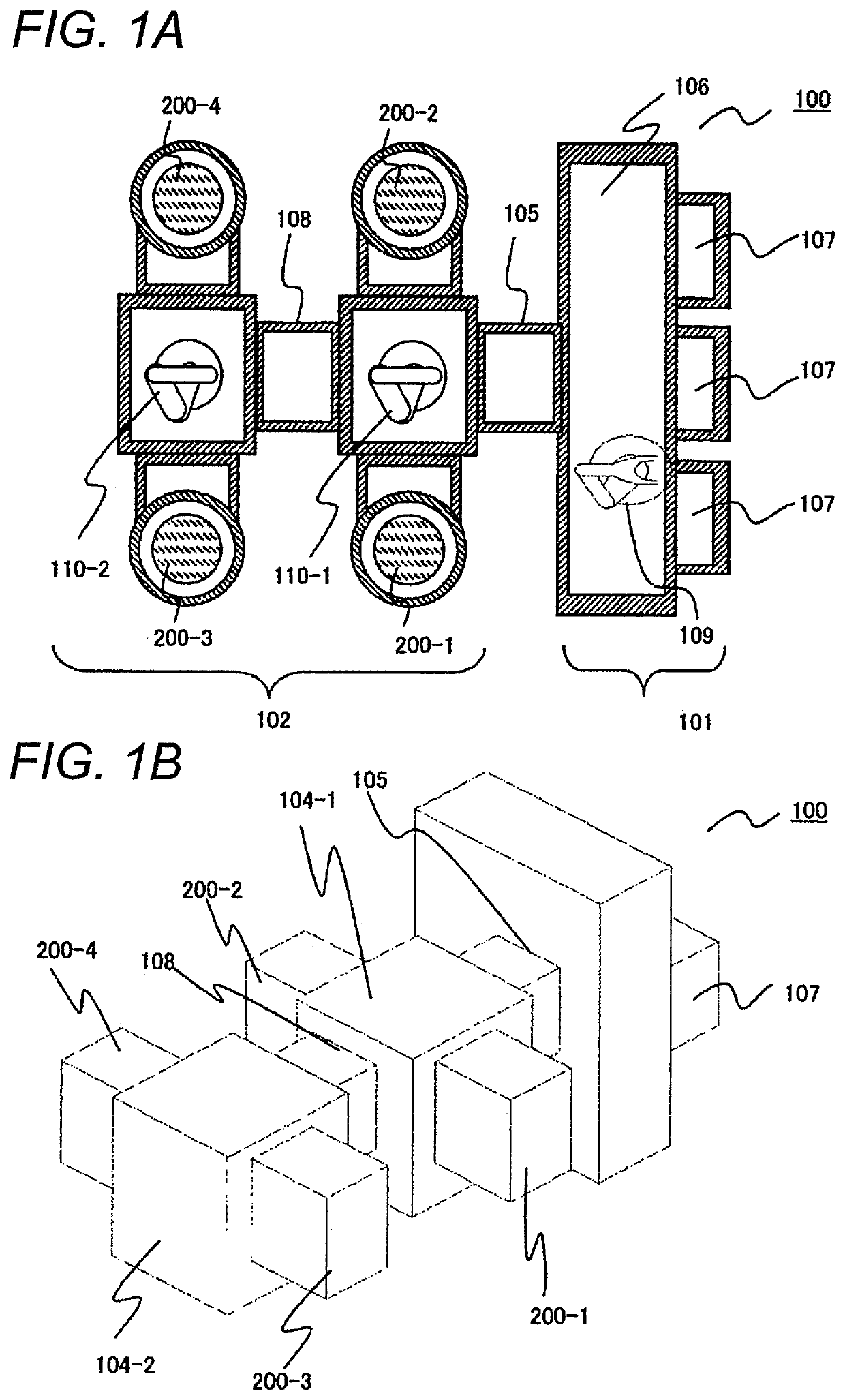
[0036]FIGS. 1A and 1B are diagrams illustrating schematically a configuration of a vacuum processing apparatus according to an example of the present invention. FIG. 1A is a transverse cross-sectional view of a vacuum processing apparatus 100 seen from above according to the example, and FIG. 1B is a perspective view of the vacuum processing apparatus 100 according to the example.

[0037]The vacuum processing apparatus 100 in the example includes an air block 101 arranged at the front side (the right side in FIGS. 1A and 1B) and a vacuum block 102 arranged at the rear side (the left side in FIGS. 1A and 1B). A substrate-like specimen such as a semiconductor wafer is transferred into the air block 101 and positioned there under air...


PUM

PropertyMeasurementUnit
pressureaaaaaaaaaa
distanceaaaaaaaaaa
angleaaaaaaaaaa

Abstract

A plasma processing apparatus has a vacuum container having a processing chamber in which a wafer is processed by plasma and at least one member constituting the vacuum container movable and detachable in a horizontal direction with respect to a base plate. The plasma processing apparatus includes a lifter arranged at a side of the vacuum container across the vacuum container on the base plate, coupled to an end portion on the opposite side of a vacuum transfer chamber on which the wafer is transferred in a decompressed interior, and having a vertical shaft to move the detachable member vertically. The lifter includes: a coupling portion coupled to the vertical shaft and the detachable member and moved along the vertical shaft; and a turning shaft being a joint portion arranged at the coupling portion and having a vertical rotational shaft, the detachable member being horizontally turned around the turning shaft.

Description

BACKGROUND OF THE INVENTION[0001]1. Field of the Invention[0002]The present invention relates to a plasma processing apparatus that processes a substrate-like specimen such as a semiconductor wafer transferred and arranged in a decompressed processing chamber within a vacuum container by the use of plasma formed in the processing chamber, and includes a plurality of members detachably arranged at vertical positions and constituting the vacuum container.[0003]2. Description of the Related Art[0004]A generally-known semiconductor wafer manufacturing apparatus for manufacturing a semiconductor device from a substrate-like specimen such as a semiconductor wafer applies processing with plasma such as etching to a film layer to be processed of a film structure having a plurality of film layers including a mask pre-formed on the upper surface of the specimen arranged in a decompressed processing chamber within a vacuum container. In such a plasma processing apparatus, for example, a proces...

Claims


Application Information

Patent Timeline
Patent Type & Authority Patents(United States)
IPC IPC(8): C23F1/08H01L21/67H01J37/32
CPCH01J37/3288H01L21/6719H01L21/67184H01J37/32853H01J37/32807H01L21/02315H01L21/3065H01L21/32136H01L21/67069H05H1/46
Inventor UEMURA, TAKASHITAUCHI, SUSUMUSATOU, KOHEI
Owner HITACHI HIGH-TECH CORP
Learn More