Airway assist device

a technology of airway and assist device, which is applied in the field of airway assist device, can solve the problems of choking by parents of young children, unable to keep every small item capable of choking a child out of the child's reach, and children lack the safety diligence of parents, etc., and achieves the effects of simple design and construction, quick deployment, and convenient us

Active Publication Date: 2020-06-09
DECHOKER LLC
View PDF6 Cites 9 Cited by
  • Summary
  • Abstract
  • Description
  • Claims
  • Application Information

AI Technical Summary

Benefits of technology

[0007]The airway assist device of the present invention addresses the aforementioned needs in the art by providing a device that can be quickly deployed in the case of a throat fluid or other material and can remove the fluid or other material in order to help clear the person's airway. The airway assist device is designed to be very easy to use so that a person who is unfamiliar with the device can still employ the device effectively in a very rapid amount of time. A choking person can use the device on himself or herself. The airway assist device is of relatively simple design and construction so as to be relatively inexpensive to produce using standard manufacturing techniques so that it is relatively affordable to a large segment of the population.
[0008]The airway assist device is comprised of a barrel that has an open first proximal end, a first distal end that has an opening, and a hollow interior. The first distal end has an inner surface within the interior chamber. A plunger has a second proximal end and a second distal end. A plunger cap has a closed base and is affixed to the second distal end of the plunger. The plunger is slidably disposed within the barrel its second proximal end protrudes through the first proximal end of the barrel. When the plunger is inserted into the barrel and drawn outwardly through the first proximal end, suction is created within the hollow interior of the barrel and pressure equalizing air is drawn into barrel through the opening on the first distal end. When the plunger assembly is inserted into the barrel to a maximum extent (fully depressed), the plunger cap on the plunger abuts the inner surface of the first distal end of the barrel. A handle is attached to the second proximal end of the plunger and is used for manual slide control of the plunger within the barrel. A face mask has a cuff encircled dome and is connected to the barrel. A resilient tube has a first tube end attached to the opening at the first distal end of the barrel and a second tube end with the tube passing through the dome of the face mask making the second tube end of the tube is fluid flow connected with the hollow chamber of the barrel. This tube can be formed of more than one discreet section. As the plunger is drawn outwardly from the barrel, the outward draw creates suction within the interior chamber of the barrel drawing air into the barrel through the opening on the first distal end of the barrel, the air so drawn being routed into barrel via the tube which draws the air through its second tube end as a result of the suction created. An O-ring encircles the plunger cap. A relief ring encircles the plunger cap and is positioned concentric with the O-ring. The relief ring has at least one longitudinal slit on an outer surface thereof, the slit allowing air to pass therethrough and in order to regulate a pressure of the suction within the barrel. A positive pressure backflow valve is located on the first distal end of the barrel. A receptacle is fluid flow connected to the backflow valve. A sound producing device is attached to the barrel or to the plunger or to the face mask for producing an instructional audio message on use of the suction device. A retainer cap is attached to the first proximal end of the barrel and prevents withdrawal of the plunger assembly from the barrel.

Problems solved by technology

One major fear for parents of young children is choking.
While some such items may simply be disgusting, other items, can get lodged in a child's throat leading to an airway closure, either partial or full, so that the child is unable to breathe, possibly leading to death.
However, it is nearly impossible to keep every small item that is capable of choking a child out of the child's reach.
Older children may have toys that have small parts which toys the younger child can easily gain access to, especially if the older child does not clean up after playing—children tend to lack the safety diligence of parents.
While playing outside, a small child can easily place a rock or other object into his or her mouthing leading to choking.
Even the most vigilant parent cannot maintain constant visual contact with the young child.
It only takes a few seconds for a potentially disastrous situation to commence.
While emergency personnel are trained to reopen a child's breathing passage, brain damage begins after the brain has been deprived of oxygen for about three minutes, faster for younger children.
Therefore, unless trained emergency personal are onsite almost immediately after the object lodges in a child's throat, the potential for an adverse outcome is great.
Although the potential for choking tends to be highest among young children, adults are not immune from the choking potential.
Food going down the throat the wrong way can potentially lead to choking in an adult.
Even if the person is not properly trained in the Heimlich, a less than perfect attempt can dislodge the closure causing material, even if it does cause minor injury to the choking person.
However, in a relatively secluded place, such as a person's home where the person may be at home alone or only with his or her spouse, improperly lodged food has greater potential for choking.
As noted above, such summoning may not prove adequate.

Method used


Image

  • Airway assist device
  • Airway assist device
  • Airway assist device

Examples


Embodiment Construction

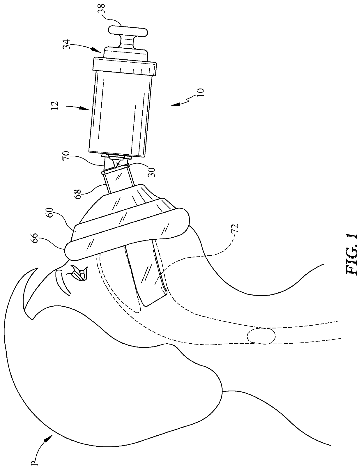
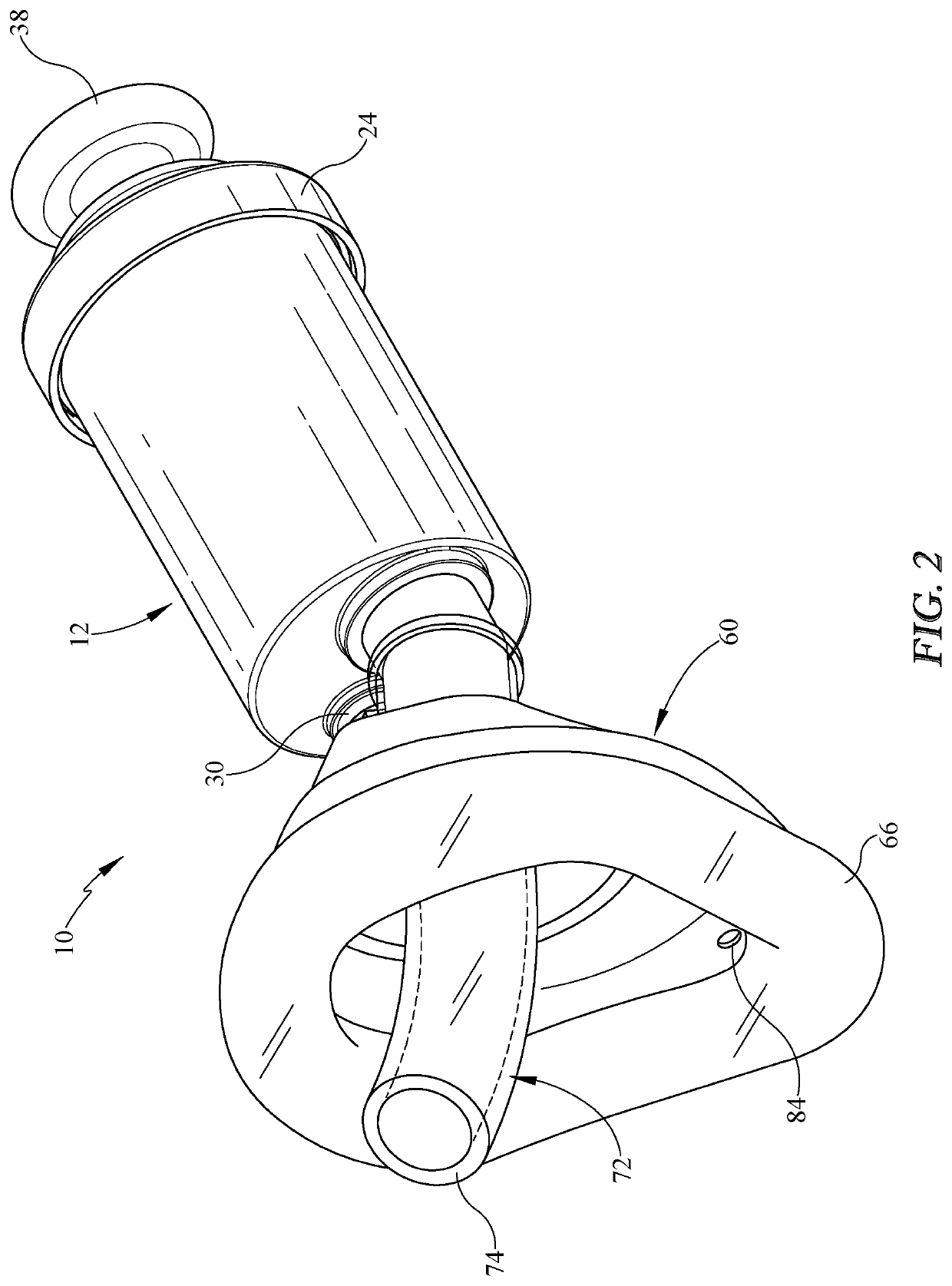
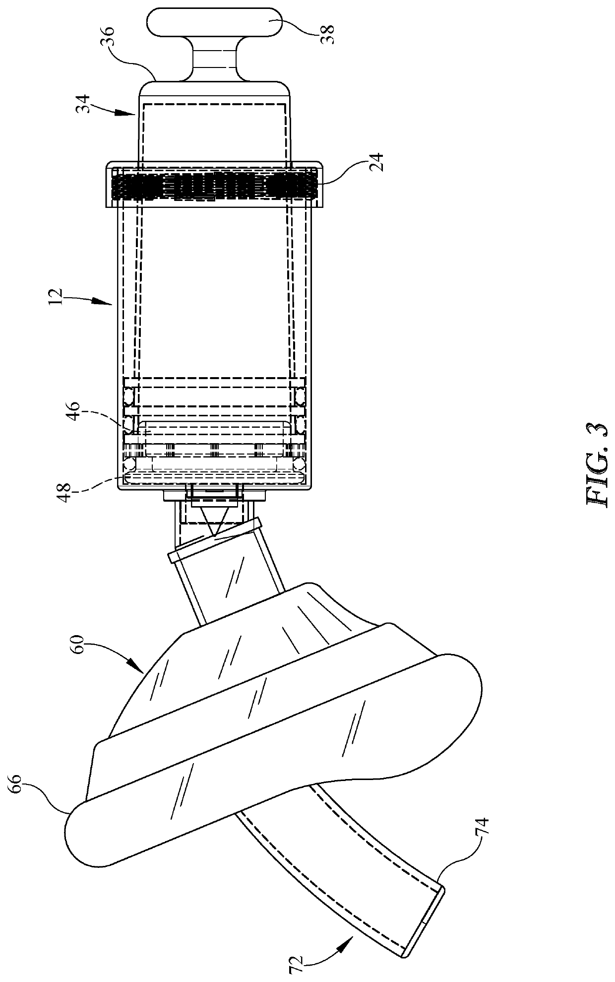
[0016]Referring now to the drawings, it is seen that the airway assist device of the present invention, generally denoted by reference numeral 10, is comprised of a barrel 12 that has an open proximal end 14 having male threading 16 thereon, a distal end 18, and a medial section 20 therebetween, the barrel 12 also having a hollow interior chamber 22. A retainer ring 24 is threadably attached to the proximal end 14 of the barrel 12, the retainer ring 24 having an inwardly directed annular lip 26. An extension 28 extends outwardly from the distal end 18 of the barrel 12, the extension 28 forming an opening via its hollow passageway such that a fluid pathway exists between the interior chamber 22 of the barrel 12 and the exterior of the extension 28. The barrel 12, the retainer ring 22 and the extension 28 are each made from an appropriate plastic or similar material, preferably a bio-acceptable material and the barrel 12 and the extension 28 may be formed as single integral unit.

[0017...


PUM


Abstract

A device that helps clear a fluid or other material lodged in a person's throat has a barrel with an open proximal end and an opening laden distal end. A plunger is slidably disposed within the barrel such that the plunger, by being manually drawn outwardly, creates suction within the barrel drawing air through the opening. A single or multi-section tube, flexible on at least its distal end, is fluid flow connected to the opening and has a face mask along its length. The distal end of the tube is intubated with a person proximate the fluid or other material so that as the plunger is drawn outwardly through the barrel, the suction created within the barrel causes air to be drawing in through the tube and into the barrel thereby helping draw out and dislodge the fluid or other material. A backflow valve located on the barrel helps clear the barrel of such things as vomit that might have been drawn into the barrel.

Description

CROSS-REFERENCE TO RELATED APPLICATIONS[0001]This application is a Continuation-in-Part of U.S. patent application Ser. No. 14 / 794,285 filed on Jul. 8, 2015, which is a Continuation-in-Part of U.S. patent application Ser. No. 13 / 830,574, filed on Mar. 14, 2013, which is a Continuation-in-Part of U.S. patent application Ser. No. 13 / 135,783, filed on Jul. 15, 2011, now abandoned, which is a Continuation-in-Part of U.S. patent application Ser. No. 12 / 928,690, filed on Dec. 15, 2010, now abandoned, which is a Continuation-in-Part of U.S. patent application Ser. No. 12 / 653,645, filed on Dec. 17, 2009, now abandoned, each application being incorporated herein by reference in its entirety.BACKGROUND OF THE INVENTION1. Field of the Invention[0002]The present invention relates to a device that is inserted into a person's mouth and helps assist in opening the person's airway due to saliva or debris present within the person's throat via suction created by the device.2. Background of the Prior...

Claims


Application Information

Patent Timeline
Patent Type & Authority Patents(United States)
IPC IPC(8): A61B17/24A61M1/00A62B18/02A61M39/24
CPCA62B18/02A61M1/0009A61B17/24A61M1/009A61M2039/2406A61M2210/0625A61M2210/065A61M1/63A61M1/67A61M1/815A61M1/962
Inventor CARVER, ALAN R
Owner DECHOKER LLC
Why Eureka
Try Eureka