
Shift range control device

a control device and shift range technology, applied in the direction of electronic commutators, mechanical equipment, stopping arrangements, etc., can solve the problems of increased friction due to motor driving, deterioration of responsiveness, and liable overshoot of actual angle of motor, so as to optimally control the driving of the motor and prevent overshoot

Active Publication Date: 2020-06-09
DENSO CORP
View PDF14 Cites 2 Cited by
  • Summary
  • Abstract
  • Description
  • Claims
  • Application Information

AI Technical Summary

Benefits of technology

[0005]An SR motor that does not use a permanent magnet has a simple configuration. In addition, a motor using a permanent magnet such as a DC brushless motor has an excellent response as compared with the SR motor.
[0007]It is an object of the present disclosure to provide a shift range control device capable of optimally controlling driving of a motor involved in switching of a shift range according to a temperature.
[0013]Since the current correction unit estimates the temperature of the motor and corrects a target motor speed, a braking timing of the motor can be advanced and overshoot can be prevented in a high temperature environment. Further, in a low temperature environment, the braking timing of the motor can be delayed, and an actual angle of the motor can be easily set to a target value. This makes it possible to optimally control the driving of the motor involved in the switching of the shift range according to the temperature.

Problems solved by technology

When the motor is used in a high temperature environment, a coil resistance of the motor is large, a flowing current is small, a braking force is lowered, and an actual angle of the motor is liable to overshoot.
On the other hand, when a motor is used in a low temperature environment, a friction due to driving of the motor increases, and a responsiveness deteriorates.

Method used


Image

  • Shift range control device
  • Shift range control device
  • Shift range control device

Examples


embodiment

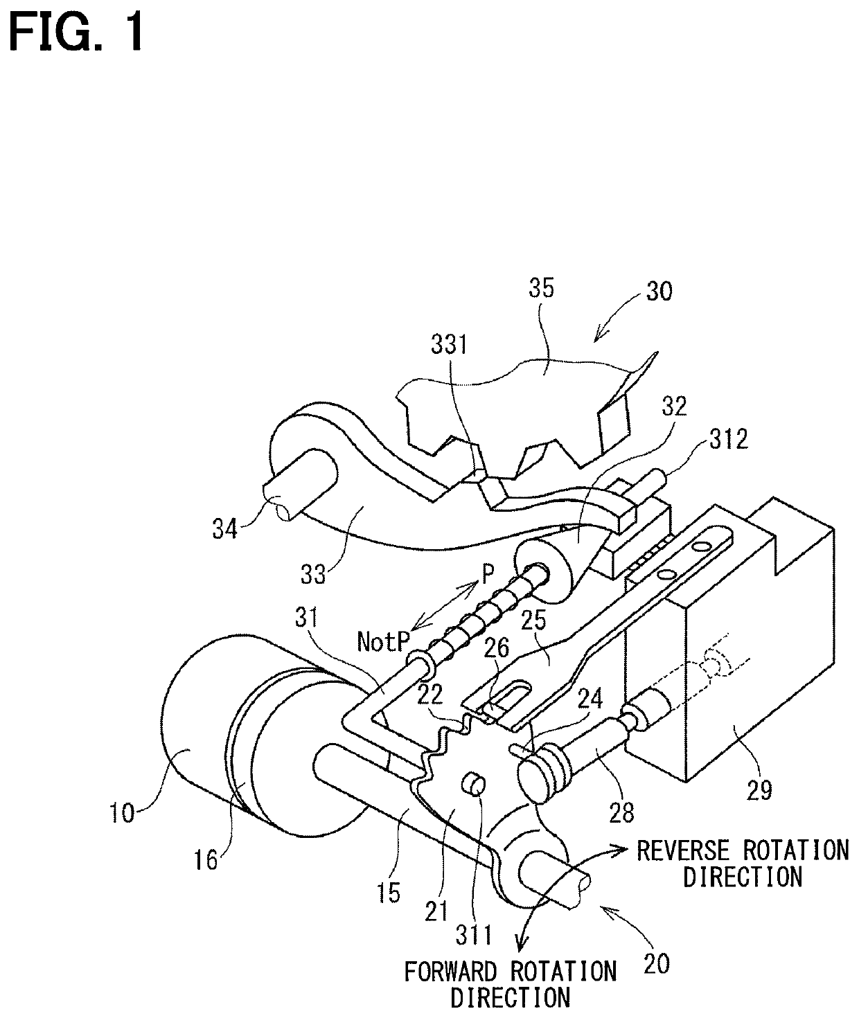
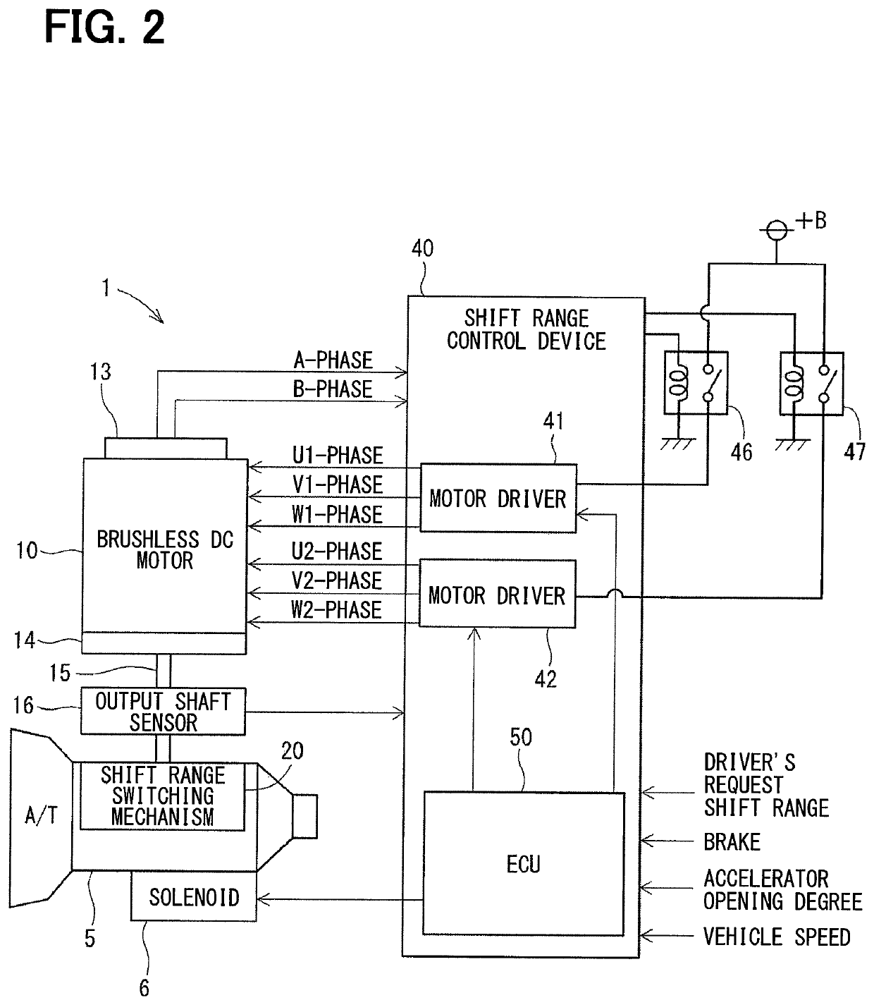
[0075]Hereinafter, the shift range control device 40 will be described.

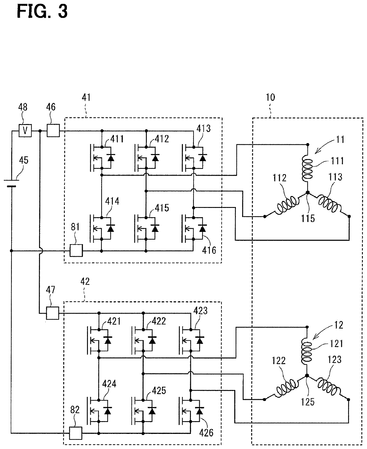
[0076]As shown in FIGS. 2 and 3, the shift range control device 40 includes motor drivers 41 and 42, motor relays 46 and 47, a voltage sensor 48, and an ECU 50.

[0077]The motor driver 41 is a three-phase inverter for switching the energization of the first winding set 11 in which switching elements 411 to 416 are bridge-connected to each other.

[0078]One end of the U1 coil 111 is connected to a connection point between the U-phase switching elements 411 and 414 that are paired with each other. One end of the V1 coil 112 is connected to a connection point between the V-phase switching elements 412 and 415 that are paired with each other. One end of the W1 coil 113 is connected to a connection point between the W-phase switching elements 413 and 416 that are paired with each other.

[0079]The other ends of the coils 111 to 113 are connected to each other by a connection portion 115.

[0080]The motor driver 42 is a three-...


PUM


Abstract

A shift range control device, mounted on a vehicle for switching a shift range by controlling a driving operation of a motor, includes: feedback controller; a feedback value setting unit; a current sensor; and a current correction unit. The feedback controller performs a feedback control based on an actual angle of the motor and a motor speed as a rotational speed of the motor. The feedback value setting unit sets a feedback value of the motor speed to advance a phase of the motor speed, based on the motor speed. The current sensor detects a motor current which flows through the motor. The current correction unit estimates a temperature of the motor based on the motor current, and corrects a target motor speed which is a target speed of the motor determined based on a request shift range.

Description

CROSS REFERENCE TO RELATED APPLICATION[0001]This application is the U.S. national phase of International Application No. PCT / JP2017 / 032361 filed Sep. 7, 2017 which designated the U.S. and claims priority to Japanese Patent Application No. 2016-176278 filed on Sep. 9, 2016, the entire contents of each of which are incorporated herein by reference.TECHNICAL FIELD[0002]The present disclosure relates to a shift range control device.BACKGROUND ART[0003]Up to now, a shift range switching device has been known which switches a shift range by controlling a motor in response to a shift range switching request from a driver. In Patent Literature 1, a switched reluctance motor is used as a driving source of a shift range switching mechanism. Hereinafter, the switched reluctance motor is referred to as an “SR motor”.PRIOR ART LITERATURESPatent Literature[0004]Patent Literature 1: Japanese Patent No. 4385768SUMMARY[0005]An SR motor that does not use a permanent magnet has a simple configuration....

Claims


Application Information

Patent Timeline
Patent Type & Authority Patents(United States)
IPC IPC(8): F16H61/32H02P29/20H02P27/06H02P6/15H02P6/28H02P29/64H02P6/24F16H59/64F16H59/72F16H59/78
CPCF16H61/32H02P6/24H02P27/06H02P29/20H02P6/153H02P6/28H02P29/64F16H59/78F16H2061/326F16H59/64F16H59/72H02P29/60
Inventor KAMIO, SHIGERU
Owner DENSO CORP
Learn More