Motor drive device including power storage unit, and motor drive system

a technology of motor drive and power storage unit, which is applied in the direction of circuit monitoring/indication, dynamo-electric converter control, transportation and packaging, etc., can solve the problems of low operating rate of converter and inverter, ineffective utilization, etc., and achieve low operating rate, cost reduction, and capacity reduction.

Active Publication Date: 2020-06-09
FANUC LTD
View PDF31 Cites 0 Cited by
  • Summary
  • Abstract
  • Description
  • Claims
  • Application Information

AI Technical Summary

Benefits of technology

[0010]A capacity of a power supply facility can be further reduced by, in a motor drive device in which a power storage unit is provided on a DC link connecting a converter to an inverter, converting AC power from an AC power supply into DC power by the converter and previously charging the DC power into the power storage unit before driving a motor, electrically detaching the motor drive device from the AC power supply when driving the motor, and covering entire electric power required for driving the motor by AC power converted by the inverter from DC power stored in the power storage unit. However, the converter does not perform a power conversion operation while the motor drive device is electrically detached from the AC power supply and the motor is driven by energy in the power storage unit; and the inverter hardly performs the power conversion operation while the motor drive device is electrically connected to the AC power supply and the power storage unit is charged. In other words, a certain degree of cost reduction by downsizing a power supply facility can be planned by providing the power storage unit; however, the converter and the inverter have low operating rates, respectively, and are not effectively utilized. Such a situation is not viewed preferable since the power conversion unit including the inverter and the converter occupies a particularly large portion of cost and space, among various types of equipment constituting the motor drive device. Accordingly, a small-sized and low-cost motor drive device including a power storage unit provided for reducing a power peak of an AC power supply, and a motor drive system are desired.

Problems solved by technology

However, the converter does not perform a power conversion operation while the motor drive device is electrically detached from the AC power supply and the motor is driven by energy in the power storage unit; and the inverter hardly performs the power conversion operation while the motor drive device is electrically connected to the AC power supply and the power storage unit is charged.
In other words, a certain degree of cost reduction by downsizing a power supply facility can be planned by providing the power storage unit; however, the converter and the inverter have low operating rates, respectively, and are not effectively utilized.
Such a situation is not viewed preferable since the power conversion unit including the inverter and the converter occupies a particularly large portion of cost and space, among various types of equipment constituting the motor drive device.

Method used


Image

  • Motor drive device including power storage unit, and motor drive system
  • Motor drive device including power storage unit, and motor drive system
  • Motor drive device including power storage unit, and motor drive system

Examples


first embodiment

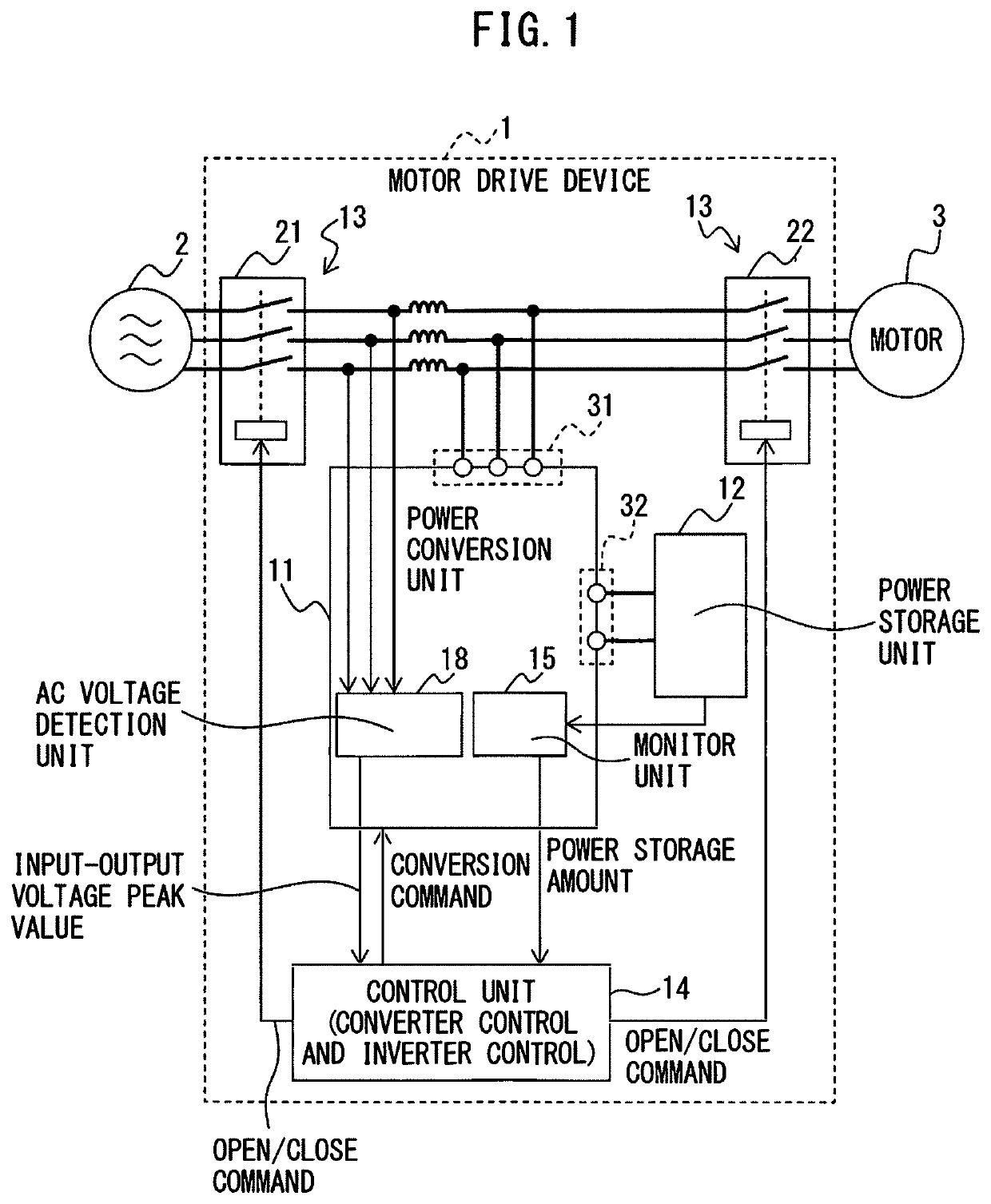
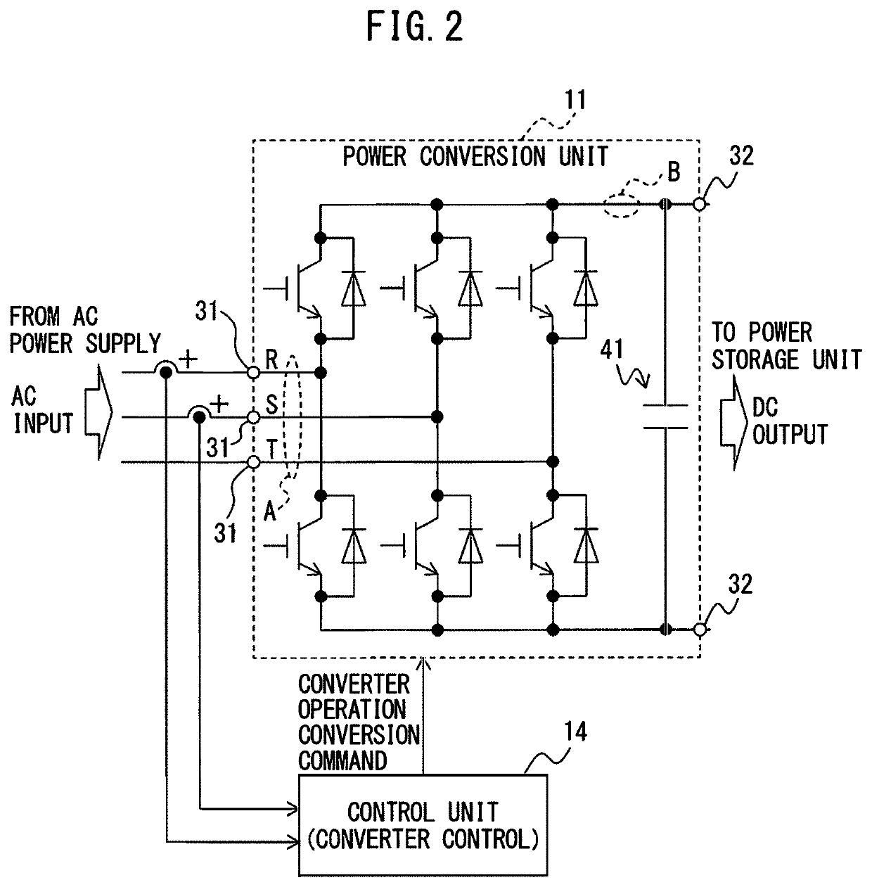
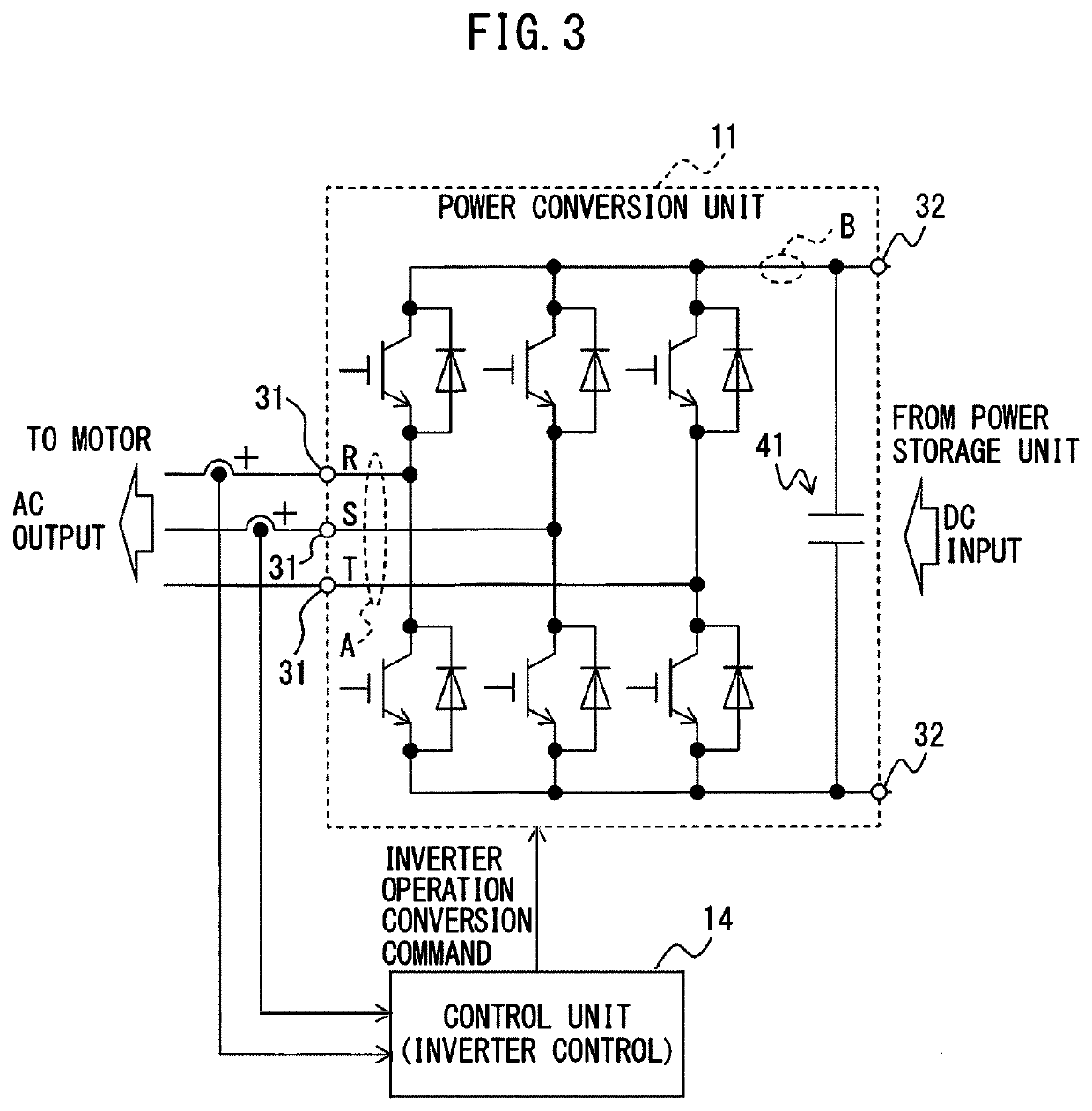
[0062]A motor drive system includes the motor drive device 1 described with reference to FIGS. 1 to 4, and an inverter.

[0063]FIG. 5 is a diagram illustrating a motor drive system driving a multi-winding-type motor, according to the first embodiment. Although a case of controlling a double-winding-type motor 5 by a motor drive system 101 according to the first embodiment will be described as an example in FIG. 5, a number of windings of the multi-winding-type motor 5 may be three or more. Further, FIG. 6 is a diagram illustrating the motor drive system driving a plurality of motors, according to the first embodiment. Although a case of controlling two single-winding-type motors 3 by the motor drive system 101 according to the first embodiment will be described as an example in FIG. 6, a number of motors 3 may be three or more.

[0064]The motor drive system 101 according to the first embodiment includes the motor drive device 1 described with reference to FIGS. 1 to 4, and an inverter ...

second embodiment

[0068]A motor drive system includes a plurality of the motor drive devices 1 described with reference to FIGS. 1 to 4.

[0069]FIG. 7 is a diagram illustrating the motor drive system driving a plurality of motors 3, according to the second embodiment, and particularly illustrates a case of an integrated control unit 16 being provided in one of the motor drive devices 1. FIG. 8 is a diagram illustrating the motor drive system driving a plurality of motors 3, according to the second embodiment, and particularly illustrates a case of the integrated control units 16 being provided in a plurality of the motor drive devices 1. Further, FIG. 9 is a diagram illustrating the motor drive system driving a plurality of motors 3, according to the second embodiment, and particularly illustrates a case of the integrated control unit 16 provided outside the motor drive devices 1.

[0070]A motor drive system 102 according to the second embodiment includes a plurality of the motor drive devices 1 describ...


PUM


Abstract

A motor drive device includes a power conversion unit configured to selectively execute a converter operation of converting AC power into DC power, and an inverter operation of converting DC power into AC power for motor driving, a power storage unit configured to store DC power output from the power conversion unit and also supply DC power to the power conversion unit, a switching unit configured to switch between an AC power supply and a motor a connection destination of the power conversion unit, and a control unit configured to control the switching unit to have the power conversion unit connected to the AC power supply and control the power conversion unit to have the converter operation executed, and configured to control the switching unit to have the power conversion unit connected to the motor and control the power conversion unit to have the inverter operation executed.

Description

RELATED APPLICATIONS[0001]The present application claims priority of Japanese Application Number 2018-003479, filed on Jan. 12, 2018, the disclosure of which is hereby incorporated by reference herein in its entirety.BACKGROUND OF THE INVENTION1. Field of Invention[0002]The present invention relates to a motor drive device including a power storage unit, and a motor drive system.2. Description of the Related Art[0003]In a motor drive device provided to machines including a machine tool, a robot etc., AC power supplied from an AC power supply is converted into DC power by a converter (rectifier) and is output to a DC link, DC power in the DC link is further converted into AC power by an inverter, and the AC power is supplied as drive power to motors provided for respective drive axes.[0004]When a motor is acceleration or deceleration controlled by a motor drive device, a large amount of output or regeneration of AC power is required for an AC power supply in a very short period of ti...

Claims


Application Information

Patent Timeline
Patent Type & Authority Patents(United States)
IPC IPC(8): H02P27/08H02M7/5387H02P25/022H02P25/22H02P5/74H02J7/00H02J7/04
CPCH02J7/0068H02P25/22H02P5/74H02J7/007H02P27/08H02J7/0048H02M7/53871H02P25/022H02P2201/03H02P27/06H02J7/04
Inventor KUROKI, WATARU
Owner FANUC LTD
Why Eureka
Try Eureka